open-dynamic-robot-initiative / open_robot_actuator_hardware Goto Github PK
View Code? Open in Web Editor NEWHome Page: https://open-dynamic-robot-initiative.github.io
License: BSD 3-Clause "New" or "Revised" License
Home Page: https://open-dynamic-robot-initiative.github.io
License: BSD 3-Clause "New" or "Revised" License


Hi there, I need your help in proving me an idiot.
Can you please show me on the MASTER-BOARD where is the Finger Connector is connected?
Is it connected on the MICRO-DRIVER? Where?
Hi,
Thanks again for sharing this awesome project and design files. If possible, I would like to ask a rather general question: what was the design criteria to select the T- Motor Antigravity 4004, 300KV motor for the robot? The paper talks briefly on its torque characteristics and that, in general, weight is a major factor. Narrowing down, I would like to know more on your selection process, if there were any soft/hard requirements you wanted to satisfy, if you tested other motors, and any other considerations you had.
Thanks for your time!
Hi
Thank you for sharing such an awesome robotics initiative.
According to your paper in arxiv, the constant k_i relates the joint torque and the current of the motor. Since this parameter is a property of the motor, could you please comment on the experimental procedure to measure it?
Thanks!
Hi there,
this project is awesome!
I'm trying to simulate the 12DOF model and I was looking for the default motor angles when the robot stands.
Thanks!
Sorry, I cannot open quadruped_robot_12dof_v1.1.
What solidworks version did you use with quadruped_robot_12dof_v1.1 file?
Hi, I'm Pau from PAL Robotics, we have found some improvement in the part "hip_fe_module_shell" that would greatly improve cable routing. We've had problems assembling the shoulder and this would ease manufacturing without changing the robot's geometry.
Before:
After:
It only modifies the external shell and help routing. I can send you the modified part if you wish.


Hi,
Is this a good actuator candidate to be used for a robotic arm with 6 degrees of freedom? Im looking for torque, velocity and a bit of position control (not heavily critical ) what kind of repeatability can I expect from this arm and my approx payload
We are building a solo 12 in pal-robotics and we have found the cable routing around the shoulder joint very complicated. We had some issue with the cables being torn by the consecutive 90º forlds.
The assembly would be much simpler and durable if the cable channel was 3 to 5 mm wider. Would it be possible to expand the "Body Structure Hip AA Support" such that it has more room for the cabling.


Thank you.
Will the project be providing more detailed bill of materials for some of the various mechanical configurations? A huge challenge for me getting started with experimenting with a new design is sourcing all the materials. Some projects I have followed have provided a BOM for a standard configuration(with suppliers) which had me up and running in under a month.
Even if this isn't added to the project page, could one of the maintainers be encouraged to provide maybe a blog post(or several) on a build?
section:
| Part Name | Quantity | Ordering Information | Comments |
|---|---|---|---|
| Biped Leg 3DOF Right Side | 1 | Biped Leg 3DOF Documentation | Custom assembly |
| Biped Leg 3DOF Left Side | 1 | Biped Leg 3DOF Documentation | Custom assembly |
links leads to:
https://github.com/open-dynamic-robot-initiative/open_robot_actuator_hardware/blob/master/mechanics/leg_3dof_v1/README.md
but it should go to:
Hi,
First, I would say thanks for all the effort that you put on this project. Especially, the well documented steps for the open source community!
I noticed that the "Dual Motor TestBed" project STL file is missing. Therefore, I would like to kindly ask you whether you can also share that project:
Thank you in advance.
Hi all, the schematics of the foot sensor uses a voltage divider via R4/R5, which gives a reference voltage of 2.2V, which is too high for the photosensor used. As a result, the opamp never indicates an illuminated sensor. The voltage divider should rather be something around R4=51K R5=5.1K resulting in a voltage of 0.3V.
Cheers,
Jochen
Unable to print on school 3D printer until school reopen, I have a printer that the tolerance are different. I need to modify the following. Is it posible to get the step file. I was able to mod the body
Actuator Module Shell Base
Actuator Module Shell Cover
Lower Leg Structure Base
Lower Leg Structure Fork
hip_aa_module_shell_base
hip_aa_module_shell_cover
hip_fe_module_shell_base
hip_fe_module_shell_cover
upper_leg_shell_base
upper_leg_shell_cover
I decide to use a switching power supply, but how much current it may consume during normal operation at the voltage of 24V ?
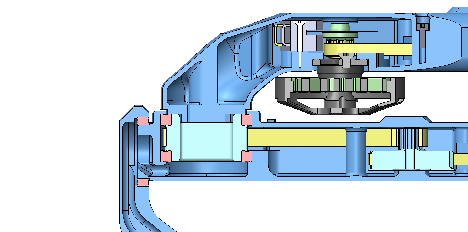
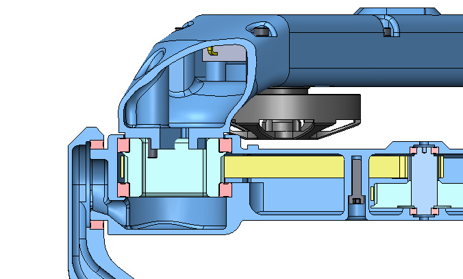
Would it be possible to produce the center pulley by wire EDM in a "2D" design, without post-processing in a lathe?
The center pulley would then be cut with a through hole like the motor pulley and a shaft would be inserted into the hole.
Would this suffice for the center pulley to be rotationally supported by its bearings or is a flat surface facing the center pulley bearings unsuitable?
I counter sink the body_structure_center, body_structure_side. Provides a larger grip surface area. Below are the flat heads I'm using. Would like the step file.
M2.5
https://www.mcmaster.com/91294a022-91294A022
M3
https://www.mcmaster.com/91294a134-91294A134

Hi, how does Foot Contact Switch v1 connect to Micro Driver ?
As I understand it connects to ADC to one of the Micro Driver MCU via U$12 contact.
Just want to get a rough idea.
Thanks.
Looking at replacing the Custom Electronic Boards with Optical Sensor
https://www.mouser.com/ProductDetail/Optek-TT-Electronics/OPB616?qs=a8pkJuPGWJ85yUPzFvMcew%3D%3D

Hi!
Thank you for share this magic project.I love this project and i want to make a quadruped robot 8dof v1 by myself.
I noticed the firmware in the "open-motor-driver-initiative" was temporarily hosted in this private repository: https://gitlab.laas.fr/open-dynamic-robot-initiative/omodri. And I can't connect to this website.This question has puzzled me for a long time.Therefore, I would like to kindly ask you whether you can also share that project.Thank you very much!
For flashing the firmware on the TI boards, we rely on the motorware repo from git-amd right now. This means anyone outside of amd-clmc won't be able to flash this board.
Is this a problem?
I noticed the Micro Driver board also supports CAN bus, why isn't this being used as communication with the main ESP32 controller. CAN bus supports up to 1Mb/s.
First off, great work! This is a great contribution to open source robotics community, very exciting. I am curious if anyone has attempted an untethered version, or done an analysis of the loads, joints, actuator sizing, etc to see if its even feasible. I understand the control scheme and electronics are currently designed for tethered operation, but I'm curious whether the hardware /actuators could be extended to an untethered build without much modification. Of course the torque/mass relationship is of utmost importance in these types of robots, and i expect that your actuators were sized for the current mass. Anyhow, I would love to build an untethered version with a custom li-ion or lipo pack, but was hoping you could share some insight or any calc/research you've done on the subject.
like what I asked in the title, how can I test the module before all stacked together?
by the way, it's really nice job.
How can I calibrate the Quadruped 12dof (Solo12) ?
Dear experts,
I am currently working on a quadruped robotics project that shares similarities with the open dynamic robots. I would greatly appreciate it if you could provide me with some resources, such as sample code or valuable research papers, to use as a reference for implementing impedance control. Thank you in advance for your assistance.
Tom
Currently, the actuaor base and cover STL files are not inluded in the list of STL files A search on the repo points to a folder in the leg_2dof_v1 where the file has 'outdated' in the name. Is this still the shell to use or is there a more recent file? Thank you!
Thank you for the great work. Where can I find the quadruped_upper_leg base and cover.
Thank you
Hi Guys,
I am using the same feet design from open dynamic. It is very good, and perform very well.
However, my system only have 5V, can I use the same design but change the supply voltage from 3v3 to 5V.
I did some testing, 5V supply can work for short term, but I do not know whether it gonna affect the life span or not.
Tom
Having problem finding the 20x25x4mm bearing locally. Is it posible to get the step file to modify for a different bearing size.
Excuse me, could you tell me what the software you have used to design your Micro Driver Electronics (pcb), looking forward to your replay. thank you very much.
The XDS100V2 appears to be discontinued and/or completely out of stock. I looked at the datasheet and V3 appears to support the same specs as V3. I think I'm going to go ahead with the V3, but if someone knows something as to why this can't be used, any suggestions would be appreciated.
Hi, Thanks for this wonderful contribution.
I wish to make the 12 DOF robot configuration.
I noticed a few things while checking the foot contact switch PCB)

The .brd file doesn't have copper pouring as shown in the Picture, sensor out track is broken, r6 is shorted . and Wire strap pins which I supposed to be external to the PCB is in the .Brd file.
Do you have the Gerber files for the foot contact switch?
Do you have SOLIDWORKS Parts of the quadruped_12dof_v1.1 ?
I need it because I currently work on the Solo head and I only find STL files.
Thanks.
I have a few questions regarding the motor shaft:
The show-stopper for me is the requirement for machined parts. Not everyone has access to the necessary equipment to make these (or the skills to use it).
Can anyone suggest how to source these parts (preferably in Europe)?
I'm sorry to bother you to tell me that what the sensors you have used in your project, and its concrete information. Now i just found only one sensor used in your wheels, right? If you have used other sensors, please offer me the information. Thanks a lot, looking forward to your reply.
Hi, I am reading about your project and soon I hope to start replicating it, could you please provide me with the electrical schematic of the whole project?
Thank you in advance.
the flat rectangle:
Do you have any instructions or advice for how to get the correct part weights for 3D resin printing without wasting a ton of time and resin? How far off can the part weight be (this isn't a very well posed question because it's too general) without the inertia measurement unit and the software failing to perform correctly?
Thank you in advance and thank you for this project.
I'm about to FDM print the lower leg part in carbon fiber. I see target weights for other parts to make sure the center of mass for the inertia control unit is correct. What infill % did you use to achieve 60g? Should this be my only carbon fiber part as far as what is strictly necessary? I would like to resin print the rest. What is suggested? What resin would you suggest? I would like to use my Elegoo Saturn. Thanks in advance.
EDIT: I can't seem to delete this. I was able to find the information I was looking for

Hi! This project is amazing! Finally, a truly open-source dog-like robot.
I'm just curious, what's the justification for using relatively uncommon AT3 belts (instead of let's say GT2). I'm sure you had a good reason, but what is it?
I understand you recommend the lower legs be manufactured using carbon fiber, but do you have some minimum strength parameters on this part? I was wondering if I might be able to resin print it using Liqcreate Strong-X (technical resin data sheet)
I know the tensile strength between carbon fiber and this resin are orders of magnitude off. I haven't done a proper in-depth project overview to get a precise understanding of the stresses on this part. Please excuse me if this is a stupid question.
Hi! Love the project. Very interested in the encoders.
How much did they cost you? An approximate idea of the build cost for the entire bot would be nice to have, and these encoders are of particular interest to me.
How did you find them in the first place? I'm always looking for better sources. Since your search-fu outdoes mine, I wish to learn your technique.
Thank you!
Hi, I want to build a drive unit to test functionalities before building 12 units of them, with some modifications with motor and sensor, here's something would you please give me some hint:
300KV 4004 from TMotor is way to expensive as a RC motor, I want to replace it with DJI Inspire 1/2 generation 3510H, same KV but smaller diameter. It has a shaft could be used as a pinon guide, and four quirky vertical tab for screw mounting. I think i can redesign the belt transmission so this is not an issue, it's for forking suggestion for people who want's build their own like me.
encoder: In the documenting https://github.com/open-dynamic-robot-initiative/open_robot_actuator_hardware/blob/master/mechanics/dual_motor_testbed_v1/README.md#dual-motor-testbed-v1 claimed it has a 5000 pulses! AB encoding with times 4 on it so the resolution is 20000 per turn. it almost impractical in my sense for a motor like this. By taking this concern I looked for its datasheet: CPR=625 and res = 5000. An AS5047 magnetic encoder with 1000 CPR would worth a compatibility/performance test. And one more favorable feature is much easier to mount the small surface polarized tablet for sensing.
How to acquire TI instaspin related code, modify the ABI settings. etc. would a stock firmware could work with ORAH software?
Thanks for the effort for the project.
A declarative, efficient, and flexible JavaScript library for building user interfaces.
🖖 Vue.js is a progressive, incrementally-adoptable JavaScript framework for building UI on the web.
TypeScript is a superset of JavaScript that compiles to clean JavaScript output.
An Open Source Machine Learning Framework for Everyone
The Web framework for perfectionists with deadlines.
A PHP framework for web artisans
Bring data to life with SVG, Canvas and HTML. 📊📈🎉
JavaScript (JS) is a lightweight interpreted programming language with first-class functions.
Some thing interesting about web. New door for the world.
A server is a program made to process requests and deliver data to clients.
Machine learning is a way of modeling and interpreting data that allows a piece of software to respond intelligently.
Some thing interesting about visualization, use data art
Some thing interesting about game, make everyone happy.
We are working to build community through open source technology. NB: members must have two-factor auth.
Open source projects and samples from Microsoft.
Google ❤️ Open Source for everyone.
Alibaba Open Source for everyone
Data-Driven Documents codes.
China tencent open source team.