Coder Social home page Coder Social logo

simplefoc / arduino-foc Goto Github PK

View Code? Open in Web Editor NEW
1.9K 73.0 498.0 10.2 MB

Arduino FOC for BLDC and Stepper motors - Arduino Based Field Oriented Control Algorithm Library

Home Page: https://docs.simplefoc.com

License: MIT License

C++ 94.06% C 5.94%
foc motor encoder arduino bldc-motor low-cost vector-control arduino-library bldc-motor-controller arduino-foc bldc-motors stepper-motor stepper-motor-control stepper-library foc-algorithm arduino-simplefoc

arduino-foc's Introduction

SimpleFOClibrary - Simple Field Oriented Control (FOC) library

A Cross-Platform FOC implementation for BLDC and Stepper motors
based on the Arduino IDE and PlatformIO

AVR build STM32 build ESP32 build RP2040 build SAMD build Teensy build

GitHub release (latest by date) GitHub Release Date GitHub commits since tagged version GitHub commit activity (branch)

arduino-library-badge License: MIT status

We live in very exciting times 😃! BLDC motors are entering the hobby community more and more and many great projects have already emerged leveraging their far superior dynamics and power capabilities. BLDC motors have numerous advantages over regular DC motors but they have one big disadvantage, the complexity of control. Even though it has become relatively easy to design and manufacture PCBs and create our own hardware solutions for driving BLDC motors the proper low-cost solutions are yet to come. One of the reasons for this is the apparent complexity of writing the BLDC driving algorithms, Field oriented control (FOC) being an example of one of the most efficient ones. The solutions that can be found on-line are almost exclusively very specific for certain hardware configuration and the microcontroller architecture used. Additionally, most of the efforts at this moment are still channeled towards the high-power applications of the BLDC motors and proper low-cost and low-power FOC supporting boards are very hard to find today and even may not exist.
Therefore this is an attempt to:

  • 🎯 Demystify FOC algorithm and make a robust but simple Arduino library: Arduino SimpleFOClibrary
    • Support as many motor + sensor + driver + mcu combinations out there
  • 🎯 Develop modular and easy to use FOC supporting BLDC driver boards

NEW RELEASE 📢 : SimpleFOClibrary v2.3.3

  • Teensy4
    • support for low-side current sensing #392
    • support for center aligned 6pwm and 3pwm (optional) #392
  • stm32
    • support for center aligned pwm (even across multiple timers and motors/drivers) #374, #388
    • support for DMA based low-side current sensing: #383,#378
    • support for f7 architecture #388,#394
  • KV rating calculation fix #347
  • Much more performant Space Vector PWM calculation #340
  • And much more:
    • See the complete list of bugfixes and new features of v2.3.3 fixes and PRs

Arduino SimpleFOClibrary v2.3.3

This video demonstrates the SimpleFOClibrary basic usage, electronic connections and shows its capabilities.

Features

  • Easy install:
    • Arduino IDE: Arduino Library Manager integration
    • PlatformIO
  • Open-Source: Full code and documentation available on github
  • Goal:
    • Support as many sensor + motor + driver + current sense combination as possible.
    • Provide the up-to-date and in-depth documentation with API references and the examples
  • Easy to setup and configure:
    • Easy hardware configuration
    • Each hardware component is a C++ object (easy to understand)
    • Easy tuning the control loops
    • SimpleFOCStudio configuration GUI tool
    • Built-in communication and monitoring
  • Cross-platform:
    • Seamless code transfer from one microcontroller family to another
    • Supports multiple MCU architectures:
      • Arduino: UNO R4, UNO, MEGA, DUE, Leonardo, Nano, Nano33 ....
      • STM32
      • ESP32
      • Teensy
      • many more ...

Documentation

Full API code documentation as well as example projects and step by step guides can be found on our docs website.

image

Getting Started

Depending on if you want to use this library as the plug and play Arduino library or you want to get insight in the algorithm and make changes there are two ways to install this code.

  • Full library installation Docs
  • PlatformIO Docs

Arduino SimpleFOClibrary installation to Arduino IDE

Arduino Library Manager

The simplest way to get hold of the library is directly by using Arduino IDE and its integrated Library Manager.

  • Open Arduino IDE and start Arduino Library Manager by clicking: Tools > Manage Libraries....
  • Search for Simple FOC library and install the latest version.
  • Reopen Arduino IDE and you should have the library examples in File > Examples > Simple FOC.

Using Github website

  • Go to the github repository
  • Click first on Clone or Download > Download ZIP.
  • Unzip it and place it in Arduino Libraries folder. Windows: Documents > Arduino > libraries.
  • Reopen Arduino IDE and you should have the library examples in File > Examples > Simple FOC.

Using terminal

  • Open terminal and run
cd #Arduino libraries folder
git clone https://github.com/simplefoc/Arduino-FOC.git
  • Reopen Arduino IDE and you should have the library examples in File > Examples > Simple FOC.

Community and contributing

For all the questions regarding the potential implementation, applications, supported hardware and similar please visit our community forum or our discord server.

It is always helpful to hear the stories/problems/suggestions of people implementing the code and you might find a lot of answered questions there already!

Github Issues & Pull requests

Please do not hesitate to leave an issue if you have problems/advices/suggestions regarding the code!

Pull requests are welcome, but let's first discuss them in community forum!

If you'd like to contribute to this project but you are not very familiar with github, don't worry, let us know either by posting at the community forum , by posting a github issue or at our discord server.

If you are familiar, we accept pull requests to the dev branch!

Arduino code example

This is a simple Arduino code example implementing the velocity control program of a BLDC motor with encoder.

NOTE: This program uses all the default control parameters.

#include <SimpleFOC.h>

//  BLDCMotor( pole_pairs )
BLDCMotor motor = BLDCMotor(11);
//  BLDCDriver( pin_pwmA, pin_pwmB, pin_pwmC, enable (optional) )
BLDCDriver3PWM driver = BLDCDriver3PWM(9, 10, 11, 8);
//  Encoder(pin_A, pin_B, CPR)
Encoder encoder = Encoder(2, 3, 2048);
// channel A and B callbacks
void doA(){encoder.handleA();}
void doB(){encoder.handleB();}


void setup() {  
  // initialize encoder hardware
  encoder.init();
  // hardware interrupt enable
  encoder.enableInterrupts(doA, doB);
  // link the motor to the sensor
  motor.linkSensor(&encoder);
  
  // power supply voltage [V]
  driver.voltage_power_supply = 12;
  // initialise driver hardware
  driver.init();
  // link driver
  motor.linkDriver(&driver);

  // set control loop type to be used
  motor.controller = MotionControlType::velocity;
  // initialize motor
  motor.init();
  
  // align encoder and start FOC
  motor.initFOC();
}

void loop() {
  // FOC algorithm function
  motor.loopFOC();

  // velocity control loop function
  // setting the target velocity or 2rad/s
  motor.move(2);
}

You can find more details in the SimpleFOC documentation.

Example projects

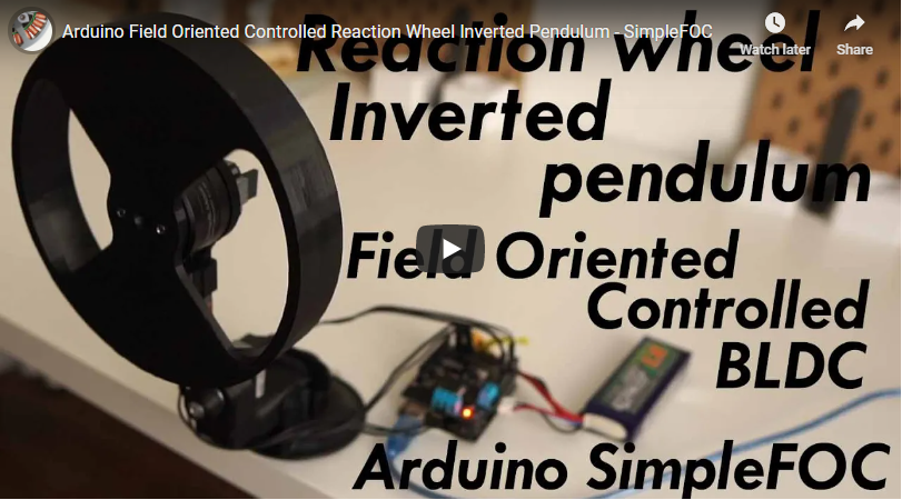
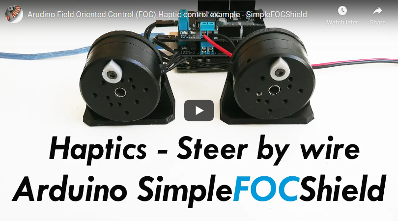
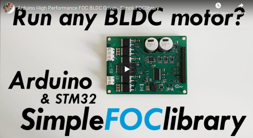
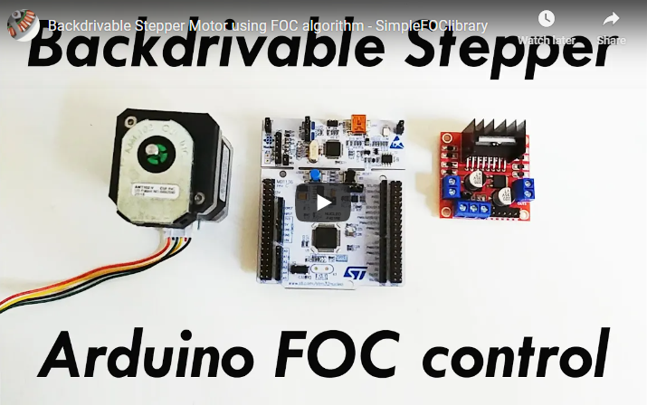
Here are some of the SimpleFOClibrary and SimpleFOCShield application examples.

Citing the SimpleFOC

We are very happy that SimpleFOClibrary has been used as a component of several research project and has made its way to several scientific papers. We are hoping that this trend is going to continue as the project matures and becomes more robust! A short resume paper about SimpleFOC has been published in the Journal of Open Source Software:

SimpleFOC: A Field Oriented Control (FOC) Library for Controlling Brushless Direct Current (BLDC) and Stepper Motors.
A. Skuric, HS. Bank, R. Unger, O. Williams, D. González-Reyes
Journal of Open Source Software, 7(74), 4232, https://doi.org/10.21105/joss.04232

If you are interested in citing SimpleFOClibrary or some other component of SimpleFOCproject in your research, we suggest you to cite our paper:

@article{simplefoc2022,
  doi = {10.21105/joss.04232},
  url = {https://doi.org/10.21105/joss.04232},
  year = {2022},
  publisher = {The Open Journal},
  volume = {7},
  number = {74},
  pages = {4232},
  author = {Antun Skuric and Hasan Sinan Bank and Richard Unger and Owen Williams and David González-Reyes},
  title = {SimpleFOC: A Field Oriented Control (FOC) Library for Controlling Brushless Direct Current (BLDC) and Stepper Motors},
  journal = {Journal of Open Source Software}
}

arduino-foc's People

Contributors

arturohernandez10 avatar askuric avatar bydagor avatar candas1 avatar candyriver avatar copper280z avatar cousinitt avatar dekutree64 avatar gagarcr avatar is4n avatar jordancormack avatar kasroka avatar maxlem avatar maxlem-neuralium avatar mcells avatar nmscode avatar owennewo avatar padok avatar pglr avatar polyphe avatar runger1101001 avatar samguns avatar sdessens avatar suryavip avatar tlalexander avatar tschundler avatar vbratasiuk avatar ystradmann avatar yuyangwang-git avatar zjor avatar

Stargazers

 avatar  avatar  avatar  avatar  avatar  avatar  avatar  avatar  avatar  avatar  avatar  avatar  avatar  avatar  avatar  avatar  avatar  avatar  avatar  avatar  avatar  avatar  avatar  avatar  avatar  avatar  avatar  avatar  avatar  avatar  avatar  avatar  avatar  avatar  avatar  avatar  avatar  avatar  avatar  avatar  avatar  avatar  avatar  avatar  avatar  avatar  avatar  avatar  avatar  avatar  avatar  avatar  avatar  avatar  avatar  avatar  avatar  avatar  avatar  avatar  avatar  avatar  avatar  avatar  avatar  avatar  avatar  avatar  avatar  avatar  avatar  avatar  avatar  avatar  avatar  avatar  avatar  avatar  avatar  avatar  avatar  avatar  avatar  avatar  avatar  avatar  avatar  avatar  avatar  avatar  avatar  avatar  avatar  avatar  avatar  avatar  avatar  avatar  avatar  avatar

Watchers

 avatar  avatar  avatar  avatar  avatar  avatar  avatar  avatar  avatar  avatar  avatar  avatar  avatar  avatar  avatar  avatar  avatar  avatar  avatar  avatar  avatar  avatar  avatar  avatar  avatar  avatar  avatar  avatar  avatar  avatar  avatar  avatar  avatar  avatar  avatar  avatar  avatar  avatar  avatar  avatar  avatar  avatar  avatar  avatar  avatar  avatar  avatar  avatar  avatar  avatar  avatar  avatar  avatar  avatar  avatar  avatar  avatar  avatar  avatar  avatar  avatar  avatar  avatar  avatar  avatar  avatar  avatar  avatar  avatar  avatar  avatar  avatar  avatar

arduino-foc's Issues

Annoying sound of the motor~

I try to learn the BLDC control with Arduino Mega2560, SimpleFoc and Ipower 5208 motor.
But the motor have some electrical sounds just like tinnitus, maybe it's because of th PWM frequency or something...
So is there anyone who can help me with this problem?
How can i change the PWM frequency?
tks!

PWM Frequency setting doesn't work on Due

I'm really only using the Due because it's got a lot of interrupt pins. If I can figure out how to use pin interrupts for rotary encoders on the 328p this won't be as big of a deal. Either way it'd still be a nice feature. Currently I can increase it by changing the PWM_RESOLUTION field in variants.h, which works fine.

Using include guards as flags will come back to bite you

At least one file in SimpleFOC uses the include guard of an external library (here the STM32duino lib) as a flag:
https://github.com/simplefoc/Arduino-FOC/blob/master/src/drivers/hardware_specific/stm32_mcu.cpp#L4

This is dangerous. If the lib author (or anyone trying to port the library, as I did) changes the include guard, this will introduce bugs that can be difficult to track. In my case, it silently prevented SimpleFOC to compile in STM32 mode, leading to strange PWM issues.

_constrain modify Ua Ub Uc

I use 6pwm driver ,i found Ua Ub Uc voltages is modified to positive when one is negative in this function below
image

will this have effect on FOC?

Incremental encoder AS5047P using the abi interface wrong reading

Hello,

I tried to run simplefoc on the odrive board,Just use the AS5047P AB interface and ignore the I interface,It runs normally. But I tried to use the I interface, The Encoder read angle error.At the index signal, the signal begins to beat. When I run position closed loop, the encoder calibration is not normal.

I really don't know how to solve this problem. The Encoder ppr is 1000. Could you tell me how to solve?
Thank You for the Answers :)

Unable to get stepper turning

My issue is as follows. The motor rotates slightly during the initialisation but won't turn when using velocity or angle control. When a target is set via the terminal the amperage increases slowly untill the voltage_limit setpoint is reached. Then it will remain here and the stepper won't move.

My setup is using:

  • Arduino mega
  • VNH2SP30 motor shield from sparkfun
  • optical rotary encoder (on the stepper shaft)

For the code I'm using the velocity_control example edited to work with the motor shield

StepperMotor motor = StepperMotor(50);//, 1.4);
StepperDriver2PWM driver = StepperDriver2PWM(       5,        7,        8,        6,        4,        9,           (int)A0,           (int)A1);
Encoder encoder = Encoder(18, 19, 1200);

Issues i've found:

  • standard pwm frequency of 32khz is to high for the VNH2SP30 (max 20khz). Fixed this by changing the prescaler in the library to set the pwm frequency to 4khz
  • setting the motor coil resistance will result in no output at all. Haven't looked into why

Any ideas?

defaut constructor missing

I created a class for the FOC part of my project :

class BrushlessMotor{

    private :

    MagneticSensorSPI sensor;
    BLDCMotor motor;
    BLDCDriver3PWM driver;
}

Because these Class does not have defaut constructor, I get this error message :
src/main.cpp:36:19: error: no matching function for call to 'MagneticSensorSPI::MagneticSensorSPI()

A solution of this problem is to use InitializerList ( https://www.geeksforgeeks.org/when-do-we-use-initializer-list-in-c/ )
According to this link : When do we use Initializer List in C++?
"3) For initialization of member objects which do not have default constructor:
In the following example, an object “a” of class “A” is data member of class “B”, and “A” doesn’t have default constructor.
Initializer List must be used to initialize “a”.

But at least, it should be probably easier to have defaut constructor for each class

last link : https://stackoverflow.com/questions/12328150/class-member-without-a-default-constructor

Low default voltage for stepper in open loop example

Awesome library!

Was just testing out some steppers with an l298n and a Teensy.
Thought I had an issue with the setup. Just got a hum out of the motors with no movement so I suspected I'd wired up the coils wrong. I think it might be that the default voltage for these open loop examples was lower than the required voltage for my stepper... Not sure.

See position example and velocity example

Is this likely to have caused this? when I raised this value the stepper seemed to work as expected. If so is it worth increasing this value or adding a comment?

esp32_position_control example does not compile for ESP32 Wrover Module

Hello,
I was using the Arduino-FOC with the STM32 which worked nicely.
Now I set it up with an ESP32 Wrover (board version 1.0.4), trying both the current master-branch and dev-branch (31.08.20) and it does not compile. the ...\examples\hardware_specific_examples\ESP32\magnetic_sensor\esp32_position_control .

Arduino throws the following error message:

`C:\Users\Josefin\Documents\Arduino\libraries\Arduino-FOC-dev\src\FOCutils.cpp: In function 'void _setPwmFrequency(int, int, int)':

C:\Users\Josefin\Documents\Arduino\libraries\Arduino-FOC-dev\src\FOCutils.cpp:108:55: error: 'MCPWM_SELECT_SYNC_INT0' was not declared in this scope

mcpwm_sync_enable(m_slot.mcpwm_unit, MCPWM_TIMER_0, MCPWM_SELECT_SYNC_INT0, 0);`

How can I fix this?
Thanks for your help!

ESP32 mcpwm_get_frequency: division by zero

Problem
This line causes a division by zero when running the code on an ESP32:

mcpwm_init(mcpwm_unit, MCPWM_TIMER_0, &pwm_config); //Configure PWM0A & PWM0B with above settings

Cause
The ESP32 Arduino Release 1.0.6 uses ESP-IDF 3.3.5
In ESP-IDF 3.3 in mcpwm.c, function mcpwm_set_frequency() called by mcpwm_init() does a division by frequency:
https://github.com/espressif/esp-idf/blob/7c86027531ebffe937c9d9d1080cd433eb993f35/components/driver/mcpwm.c#L143

Possible Resolution
To correct this, can we set pwm_config.frequency before calling mcpwm_init() ? Eg add this immediately before:
pwm_config.frequency = pwm_frequency;

Slow velocity

Hey @askuric ,

I just finished to port Your library. It was some time while I have back and implemented microsecond timer. It solved problem. I have a few issues and comments at the same time.

  1. At slow velocity motor behaves strangely. For example at 0.5 rad/s. Signal is quircky and rotation is by jumping. I think it's PI tuning needs ? I am not familiar yet with PID and and other stabilization methods.
  2. I saw that different motors need different 3 phase connections. Is it possible somehow to solve that ? it gived some time to realize it and change wiring. While simplest sine wave do not need such changing, it's practically no matter how you connect phases to motor drive, just needs to give 120 degree difference in signal.
    Maybe I am mistaken somewhere ?

motor high speed

I use sfoc lib in my own project which high speed motor 11600rpm/min and 6 MOS device, while voltage_limit must <2V, or the motor is very heat. but if if limit < 2 V ,motor speed only reach 800rpm (open loop),where I have no idea about this

questions about the support for stm32

I found that set PA8, PA9, PA10 as PWM pinout did not work.
I use the bluepill board and the code is just like this:
BLDCDriver3PWM driver = BLDCDriver3PWM(PA8,PA9, PA10)
Other pins work well, such as BLDCDriver3PWM driver = BLDCDriver3PWM(PB13, PB14, PB15) or BLDCDriver3PWM driver = BLDCDriver3PWM(PB5, PB6, PB7)

I am not sure the reason and could you help me? @owennewo

Missing LPF when monitoring current in voltage mode

All SimpleFOC data are monitored after being filtered. This allows users to tune the LPF settings. One exception though: in voltage mode, "current" values are sent to Serial without filtering. This is annoying when tuning with SimpleFOCStudio.

Unintended double promotions.

On platforms that have compiler support for doubles, such as the stm32, there are a lot of unintended float-to-double conversions in the code. I was able to reduce move() duration from 14us to 6us by eliminating just one of these unintended casts, and loopFOC() from 144us to 50us by replacing several. Almost all files have unintended promotions in them.

These instances can be easily found with -Wdouble-promotion and -Werror=double-promotion, there are a few hundred of them.

Inverse Park and Clark are being shifted incorrectly

Edit: I'm starting to think that my original statement below could be a confusion (on my part) of units/meaning of voltage_power_supply and Uq. They are all volts but the first is dc, whilst the second is 'ac peak'. I need to spend more time thinking about this (particularly which side of the fence voltage_limit sits).

Original statement:
I've spent 2 or 3 hours on this and I think I've got to the bottom of it (at least for SinePWM). The issue results in clipping of sinusoid PWM when Uq approaches voltage_power_supply. It's easier to explain when considering ControlType::voltage

I'll set out a scenario:

  • motor is in ControlType::voltage
  • with voltage_power_supply = 9
  • and voltage_limit = 9
  • and we asking for a voltage of motor.move(9)

In the above case I'd expect to see a beautiful sin wave (PWM'd) being fed to the three phases between 0 and 1.0 duty cycle. What I'm seeing is heavy clipping. Essentially dc_a,dc_b,dc_c reach a peak of ~13.5v and are being constrained (clipped) not to go over voltage_power_supply.

To remove this clipping I would change:

// Inverse park transform
Ualpha =  -_sin(angle_el) * Uq/2; 
Ubeta =  _cos(angle_el) * Uq/2;  

// Clarke transform
Ua = Ualpha + Uq/2;
Ub = -0.5 * Ualpha  + _SQRT3_2 * Ubeta + Uq/2;
Uc = -0.5 * Ualpha - _SQRT3_2 * Ubeta + Uq/2;

Change1: Uq/2 for both Ualpha and Ubeta (i.e. Ualpha and Ubeta are halved)
Change2: add Uq/2 instead of voltage_power_supply/2 to for Ua, Ub, Uc terms (i.e. changing the amount we 'shift up') in order to get the sine wave sitting exactly on zero.

Apart from empirical evidence (no clipping observed), my thinking is this.
In voltage control Uq = 9 (in above scenario)
Ualpha and Ubeta are both therefore in the range of -9v to 9v

So we are dealing with peak to peak of 18v not 9V!

If we change inverse park transform as code block above then range becomes -4.5 to 4.5V. This works well with the zero shift below.

In inverse clark transform the old code would add voltage_power_supply/2 to all Ua Ub and Uc terms meaning their range would shift to 0 to 9V.

Sounds good, however we really need to be shifting by Uq/2 not voltage_power_supply/2. (its hard to see here because Uq==voltage_power_supply in above scenario) If we consider another scenario where we are calling move(3) (i.e. Uq=3) with same voltage_power_supply = 9. Ua, Ub and Uc before shifting would be -1.5 to +1.5 sine waves. Shifting by voltage_power_supply/2 would raise it to 3 to 6v. Shifting by Uq/2 would raise to 0 to 3V. We want the latter!

I realise this a complex area, and although I think I'm right, I may have made a mistake!

I also think FOCModulationType::SpaceVectorPWM is similarly incorrect but lets focus on this case first!

False Clarke Transform in FOC

While trying to implement the foc algorithm for a delta wound linear motor, I stumbled upon a little mistake in clarke transform which resulted in unstable current control loop.

i_alpha = 0.6666667*(current.a - (current.b - current.c)); i_beta = _2_SQRT3 *( current.b - current.c );

If am not wrong It is supposed to be like this

i_alpha = 0.6666667*(current.a - current.b / 2 - current.c / 2); i_beta = 0.57735 *( current.b - current.c );

Motor Reversing/Direction change

Hi, Is there any way to reverse/change the direction of the motor? I'm also looking at using it on an stm32f103 blue pill, could the library be used with stm32? From what I can see is only the PWM high frequency function would need to be changed in order to use the stm32 clocks. I would like to use external mosfets for larger loads so that's something I will also look into. Will you implement using halls instead of the encoder? I plan on running my encoders directly to my CNC controller rather than being used for motor commutation, but I could possibly run encoder to both. Basically I want to build little FOC BLDC speed controllers using low cost blue pills for driving BLDC motors for servo control applications hobby CNC stuff using BLDC motors rather than steppers.

SpaceVector is clipping (not centered)

The SpaceVectorPWM algorithm is clipping due to it not taking into account the voltage_power_supply.

Expected behaviour:

  • the SpaceVector duty cycle for a,b,c will be centered on 0.5 duty cycle.
    Actual behaviour:
  • the duty cycle is down near zero and the signal is sometimes negative (which is then clipped)

This can result in stuttery movement or pulsing velocity. Fix is pretty simple - I'll send a PR against this issue.
Here is an unlisted youtube video - showing my setup
https://www.youtube.com/watch?v=JMZoKTe1XRA

library.properties using old URL?

Referring to:
https://github.com/simplefoc/Arduino-FOC/blob/master/library.properties
The url is

url=http://askuric.github.io/Arduino-FOC

I think you've moved the repo to simplefoc organization so has the URL changed??

In platformio I'm only able to install up to 1.3.0 which I'm guessing is when you cut over to the new git repo??

On a small but related note the space in library name "Simple FOC" is a minor inconvenience in platformio/vscode. If I have an error in compiler terminal, I can't click it to go to line number because of the space in library name (and thus space in path). I imagine changing this is risky because you'd be left with too libraries with similar names. So maybe best to do nothing about this nitpic.

__attribute__((weak)) doesn't seem to work as intended

Commit 0b7839f broke pwm control on my machine and B-G431B. The offending change appears to be:

before: src/drivers/hardware_specific/generic_mcu.cpp

#elif defined(_STM32_DEF_) // or stm32
/// do nothing
#else 
int _configure6PWM(...){ return -1; }
#endif

After: rc/drivers/hardware_specific/generic_mcu.cpp

__attribute__((weak)) int _configure6PWM(...) {return -1;}

Although this implementation is declared weak, the linker still selects this implementation for the final executable, instead of the correct one in src/drivers/hardware_specific/stm32_mcu.cpp. This problem occurs with all weakly defined implementations in this file. Simply emptying the file returns everything to working order.

I'm observing very strange behavior when debugging this issue. Sometimes, removing just one of the functions from generic_mcu.cpp fixes the issue. Sometimes, it doesn't. This suggests we're dealing with nondeterministic compiler behavior...

MagneticSensorSPI and STM32

As reported here:
https://community.simplefoc.com/t/sensor-as5047p-spi-reads-0-angle-with-stm32f103-aka-blue-pill/886/18

but also by other users, I think. It explains the difficulties some people (including myself) were having with magnetic sensors and STM32.

Here is my summary from that post:

Hey, I did a quick test setup:
[image]

  • SimpleFOC 2.1.1 master branch (current normal version of the library)
  • BluePill STM32F103C8
  • AS5047P sensor
  • PlatformIO, STM32 support v13.0
  • Motor not connected, just the sensor

I can report the following:
It actually works out of the box, with no modifications to MagneticSensorSPI.cpp.
The resulting speed is too fast for my crappy logic analyser, the oscilloscope shows the clock line is at 9MHz:
[image]
That makes sense since we set the pre-scaler to 8, and 72MHz system clock / 8 = 9MHz SPI clock in this case.

Surprisingly, this is working fine even via the SPI hub and all the cables:
[image]
With my suggested modifications to MagneticSensorSPI, the picture changes to:
[image]
So now we don’t set the pre-scaler, but rather allow beginTransaction() to apply the clock_speed as specified in the settings object.
So we get 1MHz SPI clock, as specified in the settings.

To me this confirms the following:

the standard settings kind of work with STM32. But the bus speed does not get set, via the settings, resulting in a MCU-dependent default bus speed via the pre-scaler setting of 8, which is often much too high. I’m surprised my setup works at 9MHz, and I think if there were a BLDC driver and motor running chances are it wouldn’t work well any more.

the current code prevents the bus speed from being set correctly on STM32, so as a result, many people will have trouble with the current code under STM32 (as we see in this thread).

No current sensing?

I'm wondering why it's possible to do FOC without sampling phase current.

About MCPWM?

What are these mistakes? How to solve this problem? thank you!

e:\Program Files (x86)\Arduino\libraries\Arduino-FOC-v.1.5.0\src\FOCutils.cpp:108:55: error: 'MCPWM_SELECT_SYNC_INT0' was not declared in this scope

mcpwm_sync_enable(m_slot.mcpwm_unit, MCPWM_TIMER_0, MCPWM_SELECT_SYNC_INT0, 0);

                                                   ^

exit status 1
Error compiling for development board esp32 dev module

Precision issue in Sensor.cpp (float precision issue)

The way the velocity is updated in the Sensor base class, and the fact that we are using a single 32 bit float to represent total angle in the first place means that motors using MagneticSensor (Halls and Encoders currently unaffected due to the way they calculate velocity in interrupts) stop after a certain number of turns (total angle).

This happens when the delta-angle being added is relatively so small compared to the total angle it is being added to, that the limited precision of float results in no numeric increase in the resulting sum float.
When this happens depends on the speed (the delta-angle's size) but seems to be around 30000 rad.

We have discussed this extensively, and opted for a solution where we store total revolutions (an integer value) and shaft angle (a float value) seperately, to ensure we have high precision no matter what the total angle.

The price of this is a slightly more complex interface to Sensors - users will have to consider the context of their operation, and ask for the angle in different ways (total angle or shaft angle) depending on the precision they need and what they're trying to do.
However, the change can be contained largely to the sensor base class, and may simplify the implementation of new sensors.

Use previous value of getAngle() in getVelocity()

At the moment the getVelocity() function of Sensor gets called from move(), and in turn calls the getAngle() function. getAngle() is also called from loopFOC().
Since reading sensors takes time and is the limiting factor for the FOC-iteration rate on fast MCUs, and a significant contributor on slow MCUs, it could be a good idea to reduce the number of sensor reads by 1 per iteration, by remembering the last value in getAngle() and using this in getVelocity().

One way to do it might be to change the signature of getAngle() to getAngle(bool refresh = true);
I'll supply a pull-request for this if I can.

I think this is especially important for slow MCUs like the ATMega328P trying to run multiple motors (like on the older gimbal controllers).

See also Forum post: https://community.simplefoc.com/t/atmega328pb-for-sfoc-control-with-two-as5600-i2c/371/12

Linear 3 fase motor design

Hi, Great work on this repo!

Im doing dev on a linear motor controller and have been looking at the SAMD51 chip supported by Arduino IDE. https://groups.google.com/forum/#!topic/openpnp/CnMdecdHXEY

Well. I just decided to change approach, and found your work.

Regarding the current sense feature you want to implement. How about we develop this feature for this specific board? The SAMD51 is running 120mhz and it would be a shame not to give it something to work with. For a linear motor to have high precision, i suspect you need to sense the current on each fase, while measuring the hall sensors. I have not read up on the 3 fase controller you have been using, but i suppose one can use your lib with 3 dual switches? (Mosfets) Would it be an option to sense the total current for all 3 fases, and use that in the calculation to decrease complexity?

motor.command() and CRLF

This confused me - so I'm raising an issue for discussion.

motor.command(String) doesn't work well with Serial set to eol=CRLF (i.e. \r\n)

With CRLF all commands are 'sets' e.g. P will set the P term to zero.

A fix for this is to either configure your serial terminal to LF (\n)
e.g. platformio (which defaults to CRLF) you could set the following in you platformio.ini

monitor_flags =
  --eol
    LF

If we wanted to be more 'tolerant' we could change the code e.g. to be:

  char GET = user_command.charAt(1) == '\n' || user_command.charAt(1) == '\r';

MagneticSensorSPI & teensy3.2

Hi .
I found a very weird bug is FOC library with Teensy 3.2.
This bug is not present compiling on Arduino Uno, so this is a teensy issue, compiling through Arduino

MagneticSensorSPI sensor = MagneticSensorSPI(AS5048_SPI, 10);

void setup() {
  // monitoring port
  Serial.begin(115200);
  Serial.print("SPI MODE ARDUINO = ");
  Serial.println(sensor.spi_mode);

As declaring 'sensor' as a global variable, sensor.spi_mode = SPI_MODE0 while the config for AS5048 expect spi_mode to be SPI_MODE1.

Now, if i declare sensor inside setup()

void setup() {
MagneticSensorSPI sensor = MagneticSensorSPI(AS5048_SPI, 10);
  // monitoring port
  Serial.begin(115200);
  Serial.print("SPI MODE ARDUINO = ");
  Serial.println(sensor.spi_mode);

sensor.spi_mode became what it should be = SPI_MODE1

As a result, spi_mode is wrong when sensor is declared as a global variable, that make the magnetic sensor impossible to use with teensy

_micros() accuracy

Hello @askuric,
When I use _micros(), I get 75us for the loop of FOC:

t0=_micros();
motor.loopFOC();
motor.move();
t2=_micros();
Serial.print("...");
Serial.println(t2-t0);

The result is t2-t0 = 94 with a time distribution of loopFOC() @75 + a move() @19 = 94us.

And, then, when I use this, I get 20us with an oscilloscope:

GPIOA->BSRR = GPIO_BSRR_BS15;
motor.loopFOC();
GPIOA->BSRR = GPIO_BSRR_BR15;

I think there is an accuracy issue with _micros().
Maybe, use a Timer for a best accuracy as for the Atmega328, and increase the accuracy of all others measures of timing, velocity, and so on.

Best regards.

Control of hoverboard motors

I would like to control 2 hoverboard motors for a custom wheelchair project using web interface . I already have simple web interface for ESP32 microcontroller which is simple joystick which output 2 variables for reverse/forward & steering values based on joystick position. I know there are lot of hoverboard firmware available on github but none of them are suitable for my hoverboard hardware. It uses Half bridge drivers based on IR2103/FD2103 chips . Following links describe my hardware:

Hoverboard:

https://www.ebay.com/itm/Bluetooth-Hoverboard-Self-Balancing-Electric-Scooter-LED-UL2272-CE-no-Bag-Sports/353089292564?ssPageName=STRK%3AMEBIDX%3AIT&var=622283901145&_trksid=p2057872.m2749.l2649%5D

Schematic:

2.Mainboards_hoverboard_schematic.pdf

https://aidilj.com/2015/01/sensored-bldc-motor-control-with-arduino/

Is it possible to use your code with some modification to control these motors?

Thanks.

Controlling Low_side High_side dual switches

Hi

I have been reading up on the ATSAMD51 MCu since i have decided to try your lib. on this chip.

The way you have implemented the pwm driver makes sense for the motor driver ic on your shield, but if you want to control logic level mosfets (single or dual) you have to switch 6 outputs. High side and low side.

The SAMD51 can sync. pwm outputs/channels for switching/motor driving applications. This insures that the two synchronized outputs is not eg. high or low at the same time. To set this up, you have to access the registers somehow during startup, either directly or using Arduino syntax. It is a bit confusing, since i just started reading up on the datasheet.

I think i somewhere red, that this is a todo?

What are your thoughts on this?

About AS5048

Hello,

In Readme is mentioned encoder AS5048. You using it through PWM output ? I can't search anything more about it in source code.
I am interested on small project to controll smoothly BLDC and want to use Your library, but in my board I am using AS5048A through SPI and BLDC Driver DRV8313. In simply way motor rotates very well, but speed is regulated by delay time function and it has some torque ripples :( In my case I have implemented getAngle (Degree) and get Velocity (deg/s) fuctions.

I can't understood Exactly how work setPhaseVoltage and setPWM. More deeply, what type and range of data is angle (degree or rad) ? What normalizeAngle is purpose if I have accurate angle from sensor ? How to understand negative and positive voltage values if PWM operates using Period from 0 to 255 ?

Thank You for the Answers :)

PID not using the latest error for proportional term

The PID calcs have:

float PIDController::operator() (float error){
    .....
    float proportional = P * error_prev;

Shouldn't that be float proportional = P * error; ?
It's only adding a tiny bit of latency so not a serious problem but was wondering if I'm overlooking something

switch off phases completely

To 'deactivate' the driver/motor, to save batterie energy, we should have the possibility to do it by using the api.

Incorrect bit mask created in MagneticSensorSPI::read

I noticed I was getting lots of "noise" when using an AN5048A mag angle sensor. The reported sensor angle was constantly flickering between two values. The two values changed as expected when rotating the sensor, but always oscillated between two values with a very constant offset of approximately 6.3 radians.

After chasing the source of this flickering around I realised that it was probably the parity bit flickering on and off with one of the LSB's in the angle reading. After looking through the source, I found this line in the MagneticSensorSPI file.

const static word data_mask = ~(0 >> (16 - bit_resolution));

The AS5048 is a 14 bit sensor so this works out to ~(0 >> 2). Right-shifting 0b0 by 2 equals 0b0, ones-comp of 0b0 is -0 or 0b1111111111111111.

After changing this line to...

const static word data_mask = 0b11111111111111;

The flickering stopped and the reported angle behaved as expected, smoothly following the rotation of the sensor. There is still some noise in the line because of the minor bits flipping back and forth but it's barely noticeable.

Either of the lines below should work as replacement.

const static word data_mask = 0xFFFF >> (16 - bit_resolution);

const static word data_mask = pow(2, bit_resolution) - 1;

Thanks for your work on the library. Its been really helpful.

Cheers,
Josh

Recommend Projects

  • React photo React

    A declarative, efficient, and flexible JavaScript library for building user interfaces.

  • Vue.js photo Vue.js

    🖖 Vue.js is a progressive, incrementally-adoptable JavaScript framework for building UI on the web.

  • Typescript photo Typescript

    TypeScript is a superset of JavaScript that compiles to clean JavaScript output.

  • TensorFlow photo TensorFlow

    An Open Source Machine Learning Framework for Everyone

  • Django photo Django

    The Web framework for perfectionists with deadlines.

  • D3 photo D3

    Bring data to life with SVG, Canvas and HTML. 📊📈🎉

Recommend Topics

  • javascript

    JavaScript (JS) is a lightweight interpreted programming language with first-class functions.

  • web

    Some thing interesting about web. New door for the world.

  • server

    A server is a program made to process requests and deliver data to clients.

  • Machine learning

    Machine learning is a way of modeling and interpreting data that allows a piece of software to respond intelligently.

  • Game

    Some thing interesting about game, make everyone happy.

Recommend Org

  • Facebook photo Facebook

    We are working to build community through open source technology. NB: members must have two-factor auth.

  • Microsoft photo Microsoft

    Open source projects and samples from Microsoft.

  • Google photo Google

    Google ❤️ Open Source for everyone.

  • D3 photo D3

    Data-Driven Documents codes.