Coder Social home page Coder Social logo

netlistsvg's Introduction

Linux Build Status Windows Build status Gitter chat npm version npm

netlistsvg

draws an SVG schematic from a yosys JSON netlist. This can be generated the write_json command. It uses elkjs for layout.

You can see an online demo here

Installation/Usage Instructions

Command Line Interface

Install nodejs if isn't already installed.

To install the latest version from npm:

npm install -g netlistsvg

To install the latest version from source:

git clone https://github.com/nturley/netlistsvg
cd netlistsvg
npm install # install dependencies
sudo npm install -g . # install netlistsvg to system

sudo npm uninstall -g netlistsvg # uninstall from system

You can execute netlistsvg like this.

netlistsvg input_json_file [-o output_svg_file] [--skin skin_file]

The default value for the output file is out.svg.

Should work on Linux, OSX, and Windows. Running the build scripts (makefiles and the web demo) is easiest on Linux and OSX.

Web bundle

I have a web bundle hosted on github pages here: https://nturley.github.io/netlistsvg/built/netlistsvg.bundle.js It doesn't wrap ELKjs, so you'll need to include it separately. ELK creates a global variable, so you'll need to include ELKjs before netlistsvg.

In HTML it would look something like this

<script type="text/javascript" src="https://nturley.github.io/netlistsvg/elk.bundled.js"></script>
<script type="text/javascript" src="https://nturley.github.io/netlistsvg/built/netlistsvg.bundle.js"></script>

On ObservableHQ, you can require it like this.

netlistsvg = {
  var ELK = await require('https://nturley.github.io/netlistsvg/elk.bundled.js')
  window.ELK = ELK
  return require('https://nturley.github.io/netlistsvg/built/netlistsvg.bundle.js')
}

You may want to download and host your own copy.

The web bundle includes both the analog and digital skin and an example netlist for each. Using a promise would look like this.

await netlistsvg.render(netlistsvg.digitalSkin, netlistsvg.exampleDigital);

Or to log the result to console using the callback API:

netlistsvg.render(netlistsvg.digitalSkin, netlistsvg.exampleDigital, (err, result) => console.log(result));

To turn Verilog into YosysJSON in the browser, you can use YosysJS

Development

The lib/ folder contains the main source code for netlistsvg in Typescript. The built/ folder contains said source code compiled to Javascript. When wanting to make changes to netlistsvg, one should modify the Typescript source, compile to Javascript, then test their modifications.

To compile, lint, and do self-tests, run

npm test

To build the web bundle, run

npm run build-module

Examples

Here's an digital netlist produced by Yosys along with the diagram that netlistsvg created from it.

JSON Source
{
  "modules": {
    "up3down5": {
      "ports": {
        "clock": {
          "direction": "input",
          "bits": [ 2 ]
        },
        "data_in": {
          "direction": "input",
          "bits": [ 3, 4, 5, 6, 7, 8, 9, 10, 11 ]
        },
        "up": {
          "direction": "input",
          "bits": [ 12 ]
        },
        "down": {
          "direction": "input",
          "bits": [ 13 ]
        },
        "carry_out": {
          "direction": "output",
          "bits": [ 14 ]
        },
        "borrow_out": {
          "direction": "output",
          "bits": [ 15 ]
        },
        "count_out": {
          "direction": "output",
          "bits": [ 16, 17, 18, 19, 20, 21, 22, 23, 24 ]
        },
        "parity_out": {
          "direction": "output",
          "bits": [ 25 ]
        }
      },
      "cells": {
        "$add$input.v:17$3": {
          "type": "$add",
          "port_directions": {
            "A": "input",
            "B": "input",
            "Y": "output"
          },
          "connections": {
            "A": [ 16, 17, 18, 19, 20, 21, 22, 23, 24 ],
            "B": [ "1", "1" ],
            "Y": [ 26, 27, 28, 29, 30, 31, 32, 33, 34, 35 ]
          }
        },
        "$and$input.v:28$5": {
          "type": "$and",
          "port_directions": {
            "A": "input",
            "B": "input",
            "Y": "output"
          },
          "connections": {
            "A": [ 12 ],
            "B": [ 35 ],
            "Y": [ 36 ]
          }
        },
        "$and$input.v:29$6": {
          "type": "$and",
          "port_directions": {
            "A": "input",
            "B": "input",
            "Y": "output"
          },
          "connections": {
            "A": [ 13 ],
            "B": [ 37 ],
            "Y": [ 38 ]
          }
        },
        "$procdff$40": {
          "type": "$dff",
          "port_directions": {
            "CLK": "input",
            "D": "input",
            "Q": "output"
          },
          "connections": {
            "CLK": [ 2 ],
            "D": [ 39, 40, 41, 42, 43, 44, 45, 46, 47 ],
            "Q": [ 16, 17, 18, 19, 20, 21, 22, 23, 24 ]
          }
        },
        "$procdff$41": {
          "type": "$dff",
          "port_directions": {
            "CLK": "input",
            "D": "input",
            "Q": "output"
          },
          "connections": {
            "CLK": [ 2 ],
            "D": [ 36 ],
            "Q": [ 14 ]
          }
        },
        "$procdff$42": {
          "type": "$dff",
          "port_directions": {
            "CLK": "input",
            "D": "input",
            "Q": "output"
          },
          "connections": {
            "CLK": [ 2 ],
            "D": [ 38 ],
            "Q": [ 15 ]
          }
        },
        "$procdff$43": {
          "type": "$dff",
          "port_directions": {
            "CLK": "input",
            "D": "input",
            "Q": "output"
          },
          "connections": {
            "CLK": [ 2 ],
            "D": [ 48 ],
            "Q": [ 25 ]
          }
        },
        "$procmux$36": {
          "type": "$pmux",
          "port_directions": {
            "A": "input",
            "B": "input",
            "S": "input",
            "Y": "output"
          },
          "connections": {
            "A": [ 16, 17, 18, 19, 20, 21, 22, 23, 24 ],
            "B": [ 26, 27, 28, 29, 30, 31, 32, 33, 34, 49, 50, 51, 52, 53, 54, 55, 56, 57, 3, 4, 5, 6, 7, 8, 9, 10, 11 ],
            "S": [ 58, 59, 60 ],
            "Y": [ 39, 40, 41, 42, 43, 44, 45, 46, 47 ]
          }
        },
        "$procmux$37_CMP0": {
          "type": "$eq",
          "port_directions": {
            "A": "input",
            "B": "input",
            "Y": "output"
          },
          "connections": {
            "A": [ 13, 12 ],
            "B": [ "0", "1" ],
            "Y": [ 58 ]
          }
        },
        "$procmux$38_CMP0": {
          "type": "$eq",
          "port_directions": {
            "A": "input",
            "B": "input",
            "Y": "output"
          },
          "connections": {
            "A": [ 13, 12 ],
            "B": [ "1", "0" ],
            "Y": [ 59 ]
          }
        },
        "$procmux$39_CMP0": {
          "type": "$eq",
          "port_directions": {
            "A": "input",
            "B": "input",
            "Y": "output"
          },
          "connections": {
            "A": [ 13, 12 ],
            "B": [ "0", "0" ],
            "Y": [ 60 ]
          }
        },
        "$reduce_xor$input.v:27$4": {
          "type": "$reduce_xor",
          "port_directions": {
            "A": "input",
            "Y": "output"
          },
          "connections": {
            "A": [ 39, 40, 41, 42, 43, 44, 45, 46, 47 ],
            "Y": [ 48 ]
          }
        },
        "$sub$input.v:16$2": {
          "type": "$sub",
          "port_directions": {
            "A": "input",
            "B": "input",
            "Y": "output"
          },
          "connections": {
            "A": [ 16, 17, 18, 19, 20, 21, 22, 23, 24 ],
            "B": [ "1", "0", "1" ],
            "Y": [ 49, 50, 51, 52, 53, 54, 55, 56, 57, 37 ]
          }
        }
      }
    }
  }
}

example

You can also write out the JSON by hand, of course. We support JSON5 syntax.

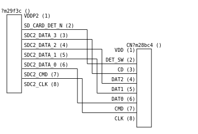
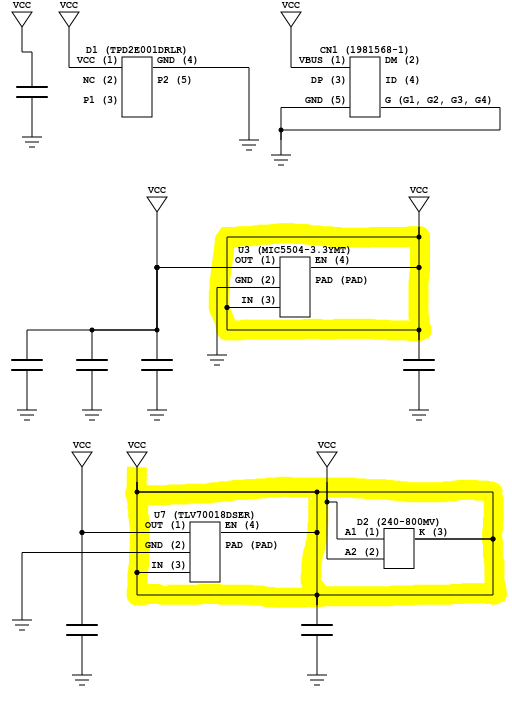
Here's an analog example.

JSON Source
{
  "modules": {
    "resistor_divider": {
      "ports": {
        "A": {
          "direction": "input",
          "bits": [2]
        },
        "B": {
          "direction": "input",
          "bits": [3]
        },
        "A AND B": {
          "direction": "output",
          "bits": [4]
        }
      },
      "cells": {
        "R1": {
          "type": "r_v",
          "connections": {
            "A": [2],
            "B": [5]
          },
          "attributes": {
            "value":"10k"
          }
        },
        "R2": {
          "type": "r_v",
          "connections": {
            "A": [3],
            "B": [5]
          },
          "attributes": {
            "value":"10k"
          }
        },
        "Q1": {
          "type": "q_pnp",
          "port_directions": {
            "C": "input",
            "B": "input",
            "E": "output"
          },
          "connections": {
            "C": [6],
            "B": [5],
            "E": [7]
          }
        },
        "R3": {
          "type": "r_v",
          "connections": {
            "A": [7],
            "B": [8]
          },
          "attributes": {
            "value":"10k"
          }
        },
        "R4": {
          "type": "r_v",
          "connections": {
            "A": [7],
            "B": [9]
          },
          "attributes": {
            "value":"10k"
          }
        },
        "R5": {
          "type": "r_v",
          "connections": {
            "A": [4],
            "B": [12]
          },
          "attributes": {
            "value":"10k"
          }
        },
        "Q2": {
          "type": "q_pnp",
          "port_directions": {
            "C": "input",
            "B": "input",
            "E": "output"
          },
          "connections": {
            "C": [10],
            "B": [9],
            "E": [4]
          }
        },
        "vcc": {
          "type": "vcc",
          "connections": {
            "A": [6]
          },
          "attributes": {
            "name":"VCC"
          }
        },
        "vcc2": {
          "type": "vcc",
          "connections": {
            "A": [10]
          },
          "attributes": {
            "name":"VCC"
          }
        },
        "gnd": {
          "type": "gnd",
          "port_directions": {
            "A": "input"
          },
          "connections": {
            "A": [8]
          },
          "attributes": {
            "name":"DGND"
          }
        },
        "gnd2": {
          "type": "gnd",
          "port_directions": {
            "A": "input"
          },
          "connections": {
            "A": [12]
          },
          "attributes": {
            "name":"DGND"
          }
        }
      }
    }
  }
}

example

Skin File

It pulls the node icons and configuration options from a SVG skin file. This our default digital skin file.

This is our analog skin file.

A skin file can use style tags or inline CSS to style the elements. That will be copied onto the output file. A skin file also defines a library of components to use. Each component has an alias list. It will use that component as a template for any cell with that type that it encounters. Each component defines the position and id of each of its ports so we know where to attach the wires to.

For example, here is a mux definition. It has two aliases: "$pmux" and "$mux". It defines a type name, and a width and height, as well as the position and id of each of it's ports. In general you can rearrange them however you like, and add whatever SVG elements you like inside the template.

<g s:type="mux" transform="translate(50, 50)" s:width="20" s:height="40">
  <s:alias val="$pmux"/>
  <s:alias val="$mux"/>

  <path d="M0,0 L20,10 L20,30 L0,40 Z"/>

  <g s:x="0" s:y="10" s:pid="A"/>
  <g s:x="0" s:y="30" s:pid="B"/>
  <g s:x="10" s:y="35" s:pid="S"/>
  <g s:x="20" s:y="20" s:pid="Y"/>
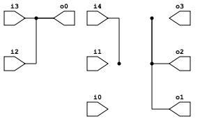
</g>

In addition to the library of components that are matched to cells, a skin file defines some special nodes. Input/Output ports, constants, Splits/Joins, and the generic node. Splits/Joins and the generic nodes are resized and ports are added or removed to adjust to the cell.

The elkjs layout properties are also defined in the skin file.

<s:layoutEngine
      org.eclipse.elk.layered.spacing.nodeNodeBetweenLayers="5"
      org.eclipse.elk.spacing.nodeNode= "35"
      org.eclipse.elk.direction="DOWN"
    />

Any properties specified here will get passed along to the layout engine. Node and edge properties aren't configurable (yet).

Using the classes .busLabel_* and .width_* (where * indicates the bus width) in the <style> tag at the top of the skin file (or the resulting svg), styling based on bus width can be added to lines and labels.

For instance, to turn off bus width labels for buses of two wires, simply add:

.busLabel_2 {
    fill-opacity: 0;
}

To change the color of all lines of width 4 to red, simply add:

line.width_4 {
    stroke: red;
}

Input JSON

Yosys JSON includes more information than we need. We only render one module (either the first or the module with an attribute "top"). If the cell name matches one of the aliases of a template from the skin, then it will use it as a template for the SVG file. Port directions are optional for cells that are defined in the skin (not generic cells).

So it should look something like this.

{
  "modules": {
    "<dont care>": {
      "ports": {
        "<port name>": {
          "direction": "<input|output>",
          "bits": [ 2, "1", ... ]
        },
        ...
      },
      "cells": {
        "<cell name>": {
          "type": "<type name>",
          "parameters": {
            "WIDTH": 3,
            ...
          },
          "port_directions": {
            "<port name>": "<input|output>",
            ...
          },
          "connections": {
            "<port name>": [ 3, "0", ... ],
            ...
          }
      },
      ...
    }
  }
}

If the cell has a WIDTH parameter greater than 1, -bus will be appended to the end of the cell type. This is useful for changing the skin of a cell for single and multibit variants, but is currently only used for $mux (and its variants). The appended -bus will show up in the generic name above the cell for any cells that have a WIDTH parameter that aren't in the skin file provided.

ElkJS

ELK is using a layered approach (Sugiyama, Ganser), similar to dot in the Graphviz package. You can read about their algorithm here: https://rtsys.informatik.uni-kiel.de/%7Ebiblio/downloads/papers/jvlc13.pdf

Status

We are getting close to the 1.0 release. At that point, the skin file format will be considered specified and breaking changes will only happen on major version bumps.

Generating input_json_file with Yosys

Yosys from Claire Wolf can be used to generate the input_json_file using the write_json command.

Unless you are doing something special you will want to use the prep command. Some examples are provided below and you can find some runnable examples which go from Verilog to diagrams in the examples directory (with example Makefile).

Generate top level diagram

This command will generate a diagram of the top module with all the inner modules shown as boxes.

yosys -p "prep -top my_top_module; write_json output.json" input.v

Generate logic diagram

You can give it the -flatten argument to the prep command if you want Yosys to convert everything into low level logic. Only basic logic cells and black boxes will exist after flattening.

yosys -p "prep -top my_top_module -flatten; write_json output.json" input.v

Generate AND (or not) and inverter (NOT) diagram

It is also frequently common that you want to create a diagram only using AND and NOT (or NAND and NOT) cells. (This is called an AIG.) This can be done with Yosys' aigmap command.

yosys -p "prep -top my_top_module; aigmap; write_json output.json" input.v

netlistsvg's People

Contributors

amstan avatar aubreyand avatar autives avatar djwubs avatar dvc94ch avatar kasbah avatar mattvenn avatar mithro avatar nobodywasishere avatar nturley avatar rjordans avatar xesscorp avatar zottel avatar

Stargazers

 avatar  avatar  avatar  avatar  avatar  avatar  avatar  avatar  avatar  avatar  avatar  avatar  avatar  avatar  avatar  avatar  avatar  avatar  avatar  avatar  avatar  avatar  avatar  avatar  avatar  avatar  avatar  avatar  avatar  avatar  avatar  avatar  avatar  avatar  avatar  avatar  avatar  avatar  avatar  avatar  avatar  avatar  avatar  avatar  avatar  avatar  avatar  avatar  avatar  avatar  avatar  avatar  avatar  avatar  avatar  avatar  avatar  avatar  avatar  avatar  avatar  avatar  avatar  avatar  avatar  avatar  avatar  avatar  avatar  avatar  avatar  avatar  avatar  avatar  avatar  avatar  avatar  avatar  avatar  avatar  avatar  avatar  avatar  avatar  avatar  avatar  avatar  avatar  avatar  avatar  avatar  avatar  avatar  avatar  avatar  avatar  avatar  avatar  avatar  avatar

Watchers

 avatar  avatar  avatar  avatar  avatar  avatar  avatar  avatar  avatar  avatar  avatar  avatar  avatar  avatar  avatar  avatar  avatar  avatar  avatar  avatar  avatar  avatar  avatar  avatar

netlistsvg's Issues

Edge ids in ELK layout input are non-unique

Doesn't actually seem to cause any problems as far as I can see but if you look at the kgraph variable you will see something like:

edges: 
   [ { id: 'eundefined',
       source: 'Q',
       sourcePort: 'Q.E',
       target: 'C1',
       targetPort: 'C1.A',
       layoutOptions: [Object] },
     { id: 'eNaN',
       source: 'Q',
       sourcePort: 'Q.E',
       target: 'R2',
       targetPort: 'R2.A',
       layoutOptions: [Object] },
     { id: 'eundefined',
       source: 'vin',
       sourcePort: 'vin.Y',
       target: 'C2',
       targetPort: 'C2.B',
       layoutOptions: [Object] },
     { id: 'eundefined',
       source: 'R1',
       sourcePort: 'R1.B',
       target: 'vout',
       targetPort: 'vout.A',
       layoutOptions: [Object] },
     { id: 'eundefined',
       source: 'vout',
       sourcePort: 'vout.A',
       target: 'Q',
       targetPort: 'Q.C',
       layoutOptions: [Object] },
   ...

Nets that should stay parallel get tangled up

I wanted to draw a page of a bigger schematic that would focus only on the SD card interface.

Something like this:
proper sd card interface schematic

Usually you have a very small subset of the SOC on one side, the sd card connector on the other side. You might see pull up resistors, some inline resistors.

Netlistsvg wasn't very happy though. Even without any resistors.
Screenshot_20190426_171245

source.json
{
	"modules": {
		"SVG Output": {
			"cells": {
				"U?m29f3c()": {
					"connections": {
						"VDDP2 (1)": [
							0
						],
						"SD_CARD_DET_N (2)": [
							1
						],
						"SDC2_DATA_3 (3)": [
							2
						],
						"SDC2_DATA_2 (4)": [
							3
						],
						"SDC2_DATA_1 (5)": [
							4
						],
						"SDC2_DATA_0 (6)": [
							5
						],
						"SDC2_CMD (7)": [
							6
						],
						"SDC2_CLK (8)": [
							7
						]
					},
					"port_directions": {
						"VDDP2 (1)": "output",
						"SD_CARD_DET_N (2)": "output",
						"SDC2_DATA_3 (3)": "output",
						"SDC2_DATA_2 (4)": "output",
						"SDC2_DATA_1 (5)": "output",
						"SDC2_DATA_0 (6)": "output",
						"SDC2_CMD (7)": "output",
						"SDC2_CLK (8)": "output"
					},
					"type": "U?m29f3c ()"
				},
				"CN?m28bc4()": {
					"connections": {
						"VDD (1)": [
							8
						],
						"DET_SW (2)": [
							1
						],
						"CD (3)": [
							2
						],
						"DAT2 (4)": [
							3
						],
						"DAT1 (5)": [
							4
						],
						"DAT0 (6)": [
							5
						],
						"CMD (7)": [
							6
						],
						"CLK (8)": [
							9
						]
					},
					"port_directions": {
						"VDD (1)": "input",
						"DET_SW (2)": "input",
						"CD (3)": "input",
						"DAT2 (4)": "input",
						"DAT1 (5)": "input",
						"DAT0 (6)": "input",
						"CMD (7)": "input",
						"CLK (8)": "input"
					},
					"type": "CN?m28bc4 ()"
				}
			},
			"ports": {}
		}
	}
}

Note that the nets are actually in the proper order, it's not like they're swapped.
Swapping the cell order does make a little bit of a difference, but there's still tangled up nets.

Port swapping

There are some pins whose position are arbitrary. The layout engine should be able to move them around to reduce wire crossings.

Add analog example to README

IMO the analog skin still doesn't work nearly as well as the digital one, but it is still picking up users. We should add at least one analog example to help analog users get started.

Better horizontal analog flow

We might be able to get better analog layouts with a horizontal flow instead of a vertical flow. The convention of VCC on top and GND on bottom might be harder to enforce.

Hyper Edge Support

For digital circuits, all nets are guaranteed to have exactly one output port (the driver), and zero or more input ports (the riders). netlistsvg had a requirement that one or more riders were required on every net until #4 was fixed.

There are some diagrams that those requirements don't make sense. Ideally block diagrams should be able to connect any collection of ports, regardless of their stated direction. Edges with multiple sources and targets are considered hyper edges.

Klayjs couldn't even properly represent hype redges in the kgraph json. Elkjs can represent hyper edges in kgraph, but layered layout doesn't support it, it supports multi edges, which is where multiple edges can use the same port as a source or a target. Using multiple edges with orthogonal routing forces edges to be on top of each other so they usually look like hyper edges. They also emit joint points where the edges join or split which we draw black circles at. I've seen some ugly cases where the same edges will split and merge together again, which looks bad but isn't incorrect, just ugly.

UPDATE: The splitting and merging hyper edges issue is a known issue: eclipse/elk#234

elklayout

Hyper Edge support from netlistsvg would look like the following

  • Multiple ports can use the same net
    • addConstants, addSplitsJoins, and createWires need to be refactored or bypassed for this to work properly
  • If there are no drivers or riders for a net, a dummy node should be created
    • dummy nodes would be invisible 0x0 nodes with one port

Error: start and end arent orthogonal

I'm using your wonderful project to draw smaller sections of my schematic.

I keep getting "Error: start and end arent orthogonal" depending on how I slice my circuit or how many things I decide to put in the circuit.

amstan@amstan-desktop:~/examples (master*)% nodejs ~/netlistsvg/bin/netlistsvg.js --skin ~/netlistsvg/lib/analog.svg out_bad.json
Error: start and end arent orthogonal
at which_dir (/home/amstan/netlistsvg/built/drawModule.js:68:15)
at /home/amstan/netlistsvg/built/drawModule.js:132:24
at Array.map (<anonymous>)
at _loop_1 (/home/amstan/netlistsvg/built/drawModule.js:120:30)
at removeDummyEdges (/home/amstan/netlistsvg/built/drawModule.js:156:23)
at Object.drawModule [as default] (/home/amstan/netlistsvg/built/drawModule.js:18:5)
at /home/amstan/netlistsvg/built/index.js:25:57

examples.zip

See out_bad.json for an example that would fail it.
I eventually tracked it down to the last 2 parts (GND430 and C5). If I remove them (out_good.json is exactly that), then netlistsvg is happy with it.
Another workaround was to make the cap's (C5) port_directions both output.

Demo webpage looks bad in Safari

I think mostly it's the fonts. It uses a serif font for test, a sans-serif font for buttons, and the textarea font isn't fixed width.

Hierarchal designs

This stood out to me on the README before but was removed in some re-shuffling and I couldn't see an issue for it.

Yosysjs and klayjs are both capable of handling sub circuits and subgraphs. It might be interesting to see what kind of images I can produce from a hierarchal design.

I guess the more interesting thing to me would be to allow navigating hierarchies in an interactive fashion but that may be out of scope for this project.

Separate out node functionality so it can be used in browsers

The fs calls could all be put into bin/. It could then be npm installed and packaged with browserify, webpack or similar by users.

I propose this as the main function:

netlistSvg(input, [options], done)

Param Type Description
input Object Parsed JSON netlist as a JS object
[options] Object Optional options
done function Callback function of the form function(err, result) where the result is the string of SVG data

Alternatively, if we can adopt ES6, it could return a Promise instead of having a callback function though, with the form above, the function lends itself to promisify utility functions from Node and Bluebird anyway.

Indicate bus width

Would be nice to be able to easily see the width of buses other than from the splits and constants.

How to generate from an NGSPICE netlist?

sent via email

It's possible to use the "analog.svg" library to draw a analog schematic from NGSPICE netlist?

In other words, how to convert a NGSPICE netlist to yosys JSON netlist ?

If you think that this is possible, may you give me an example of a yosys JSON netlist equivalent to this simple NGSPICE netlist (using "analog.svg") ? (don't need to be complete, just a partial functional example can help me to understand the rest)

Vcc 1 0 dc 5
Vs 50 0 0.0 ac 1 sin(0 2 10k)
Rs 50 2 100
RL 3 0 2k
Q1 4 2 0 QNPN
R1 1 4 2.0e3
C1 4 3 2.0e-9

image

compatible with observablehq

It would be neat to be able to render schematics in an observablehq notebook. It looks like the way that netlistsvg is packaged makes it a little tricky to import.

Allow vertical generic ports

Currently, the generic component puts all inputs on the left and output ports on the right. There should be a way to put ports on the top and bottom as well.

allow setting port directions in the skin

Since the port direction is really geometric information and not electrical information it should/could be defined in the skin directly, and should be renamed to top, bottom, left and right or north, south, east and west.

When multiple modules exist, netlistsvg just uses the first one.

If you have multiple modules in your JSON file, netlistsvg uses the first one found in the file. As yosys outputs an alphabetically ordered file, this isn't probably what people want.

Instead they probably want the module which is marked as the 'top'; see below;

    "MUX4": {
      "attributes": {
        "top": 1,
        "src": "sim.v:3"
      },
      "ports": {
        "I0": {
          "direction": "input",
          "bits": [ 2 ]
        },
        "I1": {

ignoring position attribute on ports

In the typescript migration I think I broke s:position attribute so it is now ignored. As soon as we have unit tests up and running that should prevent this kind of breakage in the future.

constant behavior should be parameterizable by the skin

Currently, all unique sequences of 0's and 1's triggers the creation of a constant node. Ideally, the skin file would define

  • what signal values represent constants
  • whether to merge all constant nodes or to create a constant for every occurrence of those signal values

Support for nested netlists?

Looking at the ELK page they have this diagram;
image

Looking at the channel 1 and channel 2 sections, this diagram shows support for "diagram inside a diagram" type thing.

It would be really cool to be able to nest a netlist inside another netlist and use this feature. Any idea how to support this and how hard it would be to add?

typescript

Hi

Anyone against using typescript in netlistsvg? Alternatively we could add a index.d.ts just declaring the types. @nturley @kasbah

netlistsvg chokes on the following JSON file generated by yosys

netlistsvg dies with the following error;

/home/tansell/github/nturley/netlistsvg/lib/index.js:732
            riders.forEach(function(r)
                  ^

TypeError: Cannot read property 'forEach' of undefined
    at /home/tansell/github/nturley/netlistsvg/lib/index.js:732:19
    at Array.forEach (native)
    at /home/tansell/github/nturley/netlistsvg/lib/index.js:725:23
    at Array.forEach (native)
    at createWires (/home/tansell/github/nturley/netlistsvg/lib/index.js:723:18)
    at /home/tansell/github/nturley/netlistsvg/lib/index.js:40:9
    at /home/tansell/github/nturley/netlistsvg/node_modules/jsonfile/index.js:46:5
    at /home/tansell/github/nturley/netlistsvg/node_modules/graceful-fs/graceful-fs.js:78:16
    at FSReqWrap.readFileAfterClose [as oncomplete] (fs.js:380:3)

with the following input JSON file;

{
  "creator": "Yosys 0.7+381 (git sha1 8f2638ae, gcc 6.3.0-18 -fPIC -Os)",
  "modules": {
    "CARRY4_COMPLETE": {
      "attributes": {
        "top": 1,
        "src": "sim.v:1"
      },
      "ports": {
        "CO": {
          "direction": "output",
          "bits": [ 2, 3, 4, 5 ]
        },
        "O": {
          "direction": "output",
          "bits": [ 6, 7, 8, 9 ]
        },
        "CIN": {
          "direction": "input",
          "bits": [ 10 ]
        },
        "DI": {
          "direction": "input",
          "bits": [ 11, 12, 13, 14 ]
        },
        "S": {
          "direction": "input",
          "bits": [ 15, 16, 17, 18 ]
        }
      },
      "cells": {
        "$ternary$sim.v:10$3": {
          "hide_name": 1,
          "type": "$mux",
          "parameters": {
            "WIDTH": 1
          },
          "attributes": {
            "src": "sim.v:10"
          },
          "port_directions": {
            "A": "input",
            "B": "input",
            "S": "input",
            "Y": "output"
          },
          "connections": {
            "A": [ 12 ],
            "B": [ 2 ],
            "S": [ 16 ],
            "Y": [ 3 ]
          }
        },
        "$ternary$sim.v:11$4": {
          "hide_name": 1,
          "type": "$mux",
          "parameters": {
            "WIDTH": 1
          },
          "attributes": {
            "src": "sim.v:11"
          },
          "port_directions": {
            "A": "input",
            "B": "input",
            "S": "input",
            "Y": "output"
          },
          "connections": {
            "A": [ 13 ],
            "B": [ 3 ],
            "S": [ 17 ],
            "Y": [ 4 ]
          }
        },
        "$ternary$sim.v:12$5": {
          "hide_name": 1,
          "type": "$mux",
          "parameters": {
            "WIDTH": 1
          },
          "attributes": {
            "src": "sim.v:12"
          },
          "port_directions": {
            "A": "input",
            "B": "input",
            "S": "input",
            "Y": "output"
          },
          "connections": {
            "A": [ 14 ],
            "B": [ 4 ],
            "S": [ 18 ],
            "Y": [ 5 ]
          }
        },
        "$ternary$sim.v:9$2": {
          "hide_name": 1,
          "type": "$mux",
          "parameters": {
            "WIDTH": 1
          },
          "attributes": {
            "src": "sim.v:9"
          },
          "port_directions": {
            "A": "input",
            "B": "input",
            "S": "input",
            "Y": "output"
          },
          "connections": {
            "A": [ 11 ],
            "B": [ 10 ],
            "S": [ 15 ],
            "Y": [ 2 ]
          }
        },
        "$xor$sim.v:8$1": {
          "hide_name": 1,
          "type": "$xor",
          "parameters": {
            "A_SIGNED": 0,
            "A_WIDTH": 4,
            "B_SIGNED": 0,
            "B_WIDTH": 4,
            "Y_WIDTH": 4
          },
          "attributes": {
            "src": "sim.v:8"
          },
          "port_directions": {
            "A": "input",
            "B": "input",
            "Y": "output"
          },
          "connections": {
            "A": [ 15, 16, 17, 18 ],
            "B": [ 10, 2, 3, 4 ],
            "Y": [ 6, 7, 8, 9 ]
          }
        }
      },
      "netnames": {
        "$ternary$sim.v:10$3_Y": {
          "hide_name": 1,
          "bits": [ 3 ],
          "attributes": {
            "src": "sim.v:10"
          }
        },
        "$ternary$sim.v:11$4_Y": {
          "hide_name": 1,
          "bits": [ 4 ],
          "attributes": {
            "src": "sim.v:11"
          }
        },
        "$ternary$sim.v:12$5_Y": {
          "hide_name": 1,
          "bits": [ 5 ],
          "attributes": {
            "src": "sim.v:12"
          }
        },
        "$ternary$sim.v:9$2_Y": {
          "hide_name": 1,
          "bits": [ 2 ],
          "attributes": {
            "src": "sim.v:9"
          }
        },
        "$xor$sim.v:8$1_Y": {
          "hide_name": 1,
          "bits": [ 6, 7, 8, 9 ],
          "attributes": {
            "src": "sim.v:8"
          }
        },
        "CIN": {
          "hide_name": 0,
          "bits": [ 10 ],
          "attributes": {
            "src": "sim.v:4"
          }
        },
        "CO": {
          "hide_name": 0,
          "bits": [ 2, 3, 4, 5 ],
          "attributes": {
            "src": "sim.v:2"
          }
        },
        "DI": {
          "hide_name": 0,
          "bits": [ 11, 12, 13, 14 ],
          "attributes": {
            "src": "sim.v:5"
          }
        },
        "O": {
          "hide_name": 0,
          "bits": [ 6, 7, 8, 9 ],
          "attributes": {
            "src": "sim.v:3"
          }
        },
        "S": {
          "hide_name": 0,
          "bits": [ 15, 16, 17, 18 ],
          "attributes": {
            "src": "sim.v:6"
          }
        }
      }
    }
  }
}

It was generated from the following verilog code;

module CARRY4_COMPLETE(CO, O, CIN, DI, S);
	output [3:0] CO;
	output [3:0] O;
	input wire CIN;
	input [3:0] DI;
	input [3:0] S;

	assign O = S ^ {CO[2:0], CIN};
	assign CO[0] = S[0] ? CIN : DI[0];
	assign CO[1] = S[1] ? CO[0] : DI[1];
	assign CO[2] = S[2] ? CO[1] : DI[2];
	assign CO[3] = S[3] ? CO[2] : DI[3];
endmodule

I've tried all of;

  • yosys -p "proc; write_json sim.json" sim.v
  • yosys -p "flatten; proc; write_json sim.json" sim.v
  • yosys -p "hierarchy -top CARRY4_COMPLETE -purge_lib; flatten; proc; write_json sim.json" sim.v

Putting some console.log statements like follows;

diff --git a/lib/index.js b/lib/index.js
index a2d705f..7f8c65a 100644
--- a/lib/index.js
+++ b/lib/index.js
@@ -714,14 +714,17 @@ function createWires(module)
     {
         n.inputPorts.forEach(function(port) {
             port.parentNode = n;
+           console.log(arrayToBitstring(port.value));
             addToDefaultDict(nets,arrayToBitstring(port.value),port);
         });
     });
     var wires = [];
+    console.log("----");
     module.nodes.forEach(function(n)
     {
         n.outputPorts.forEach(function (port) {
             port.parentNode = n;
+           console.log(arrayToBitstring(port.value));
             var riders = nets[arrayToBitstring(port.value)];
             var wire = {'drivers': [port], 'riders': riders};
             wires.push(wire);

I get the following;

,2,3,4,5,
,6,7,8,9,
,12,
,2,
,16,
,13,
,3,
,17,
,14,
,4,
,18,
,11,
,10,
,15,
,15,16,17,18,
,10,2,3,4,
,2,3,4,
,2,
,3,
,4,
,10,
,2,3,4,
,11,12,13,14,
,15,16,17,18,
----
,10,
,11,12,13,14,
,15,16,17,18,
,3,
,4,
,5,

I'm guessing that the issue is something to do with the modules?

thread safety

I think that when multiple netlists are being processed simultaneously, it causes problems in the layout. This isn't a big deal for the CLI, but using it as a library or with the browser bundle runs into this frequently.

Figure out how to support parameters

I think at the moment Yosys doesn't pass through anything about parameters, so the first thing would be to figure out if that is possible.

Then need to figure out how to display them...

Internal loader.js error

Running netlistsvg on my machine fails with the below error message, however when the generated JSON file is loaded into the online demo, it renders the netlist fine.

> yosys -p "prep -top top; write_json dance.json" top.v div.v mem.v pc.v
...
> node ../tools/netlistsvg/bin/netlistsvg.js dance.json -o dance.svg

internal/modules/cjs/loader.js:651
    throw err;
    ^

Error: Cannot find module '../built'
    at Function.Module._resolveFilename (internal/modules/cjs/loader.js:649:15)
    at Function.Module._load (internal/modules/cjs/loader.js:575:25)
    at Module.require (internal/modules/cjs/loader.js:705:19)
    at require (internal/modules/cjs/helpers.js:14:16)
...

I've noticed this was changed in commit decf30. I have tried uninstall and reinstall of npm, as well as running the makefile in the examples folder. All result in the same error.

Add a unique id to the generated elements

Hi, it would be really useful to be able to use getElementById to modify the SVG after it has been generated. My use case: I am building a web-based digital logic simulator, and I am using netlistsvg to render the components and interact with them. My guess is that many people may want to use javascript to make the graphs interactive.

I managed to figure out how to add onClick listeners to the inputs, and change the color of the wires on the fly. Showcase: SRLatch GIF, web demo.

You can see the commits on my fork, they are very short as I'm only adding a unique id:

Inputs/outputs: 683b882
Wires: 1c0ecd8

With wires it's a bit more complicated because they are made out of many segments, so I decided to add the same class tag and use CSS to change the color.

But basically, I'm only missing a way to be able to select components by id, simply getting the name of the component when I click on it would be enough for my purposes.

Thanks!

very large diagrams get limited to 8000px wide

I'm trying to get a layout of the picorv32 riscV processor drawn.
It works! (with increased node stack size!).
However, the output image is very long and thin. 8000x31000px.

Is there a way to specify an aspect ratio? I took a look at the elks documentation and couldn't find anything obvious. I grepped the source code for 8000 and only found memory limits.

Thanks for the great resource!

ports should also support multiple aliases

allowing multiple aliases for the same symbol allows us to not duplicate the same symbols for every name that yosys might give it. Having different cell types with different port names means you can't reuse the same symbol.

pass arbitrary attributes to skin

Setting classes on symbols would be great. This means that only one diode or transistor symbol is required.
The diode skin would look like this:

<g s:type="diode" s:width="20" s:height="50" transform="translate(75,280)">
   <s:alias val="d"/>
   <path d="M0,15 H20 L10,35 Z M0,35 H20" class="symbol"/>
   <path d="M10,0 V15 M10,35 V50" class="connect"/>
   <!-- schottky -->
   <path s:attr="schottky" d="M0,35 V40 M20,35 V30" class="symbol"/>
   <g s:x="10" s:y="0" s:pid="+"/>
   <g s:x="10" s:y="50" s:pid="-"/>
</g>

appveyor CI

Ideally, our tests should run on Linux and Windows. Right now, we have travis running Linux testing, but we should add Appveyor to verify our examples work on Windows.

Elkjs migration broke some properties

It definitely broke direction, and I suspect it might have broken spacing and border spacing.

You can fix the skin properties like this.

<s:properties org.eclipse.elk.direction="DOWN" />

Having periods in attribute names is apparently valid XML but looks ugly. This looks a little better

<s:properties>
  <s:layoutOption name="org.eclipse.elk.direction" value="DOWN"/>

or maybe this

<s:properties>
  <s:layoutOption>
    <s:name>org.eclipse.elk.direction</s:name>
    <s:value>DOWN</s:value>
  </s:layoutOption>

Redundant "Larry" VCCs and other connections

I keep seeing connections that are redundant. Note a lot of the VCCs, they connect one way, but then they go around the part and connect from the other side too, just to be sure. Skin doesn't seem to make a difference for my file.

out
See attachment for source json (same file as out_good.json from the other bug I submitted):
out_good.zip

I noticed the same thing happening when using the common emitter example in the demo with the analog skin selected, see base of the transistor.

I remember there used to be a rendered picture of the common_emitter circuit in the docs and it didn't have this problem.

Add text/values to parts (especially skinned)

I would like to label my resistors, capacitors with reference designators (R1, C1) and values (1k, 100nF).

Right now there's no way to add any text except by changing the type to something custom (to disable the skin), even then, would be nice to support multiple lines.

For the VCC part in the analog skin, I would like to change the text "VCC" dynamically, for designs that have more than one voltage rail. Perhaps that could be the VCC part's "value".

Another smaller request that might be related: for blocky chip type parts, a way to put the pin names inside and pin numbers outside. For now my workaround is to just have the pin numbers in () and live with the fact that everything's outside of the block.

Allow manual placement of pins

It would be good if you could specify manual location overrides for things in the generated diagram.

I mainly want this to force the input / output pins to be at a specific location.

I need this so that I can do heirachical generation of diagrams. IE Generate a diagram for the internals of a black box, then embedded that as a skin inside the next level up.

It would also be good for when you want to more control on generation.

hex constants

Right now all constants are displayed in binary. For 32 bit numbers, it looks ridiculous. We should convert to hex for anything beyond 3 bits.

Recommend Projects

  • React photo React

    A declarative, efficient, and flexible JavaScript library for building user interfaces.

  • Vue.js photo Vue.js

    ๐Ÿ–– Vue.js is a progressive, incrementally-adoptable JavaScript framework for building UI on the web.

  • Typescript photo Typescript

    TypeScript is a superset of JavaScript that compiles to clean JavaScript output.

  • TensorFlow photo TensorFlow

    An Open Source Machine Learning Framework for Everyone

  • Django photo Django

    The Web framework for perfectionists with deadlines.

  • D3 photo D3

    Bring data to life with SVG, Canvas and HTML. ๐Ÿ“Š๐Ÿ“ˆ๐ŸŽ‰

Recommend Topics

  • javascript

    JavaScript (JS) is a lightweight interpreted programming language with first-class functions.

  • web

    Some thing interesting about web. New door for the world.

  • server

    A server is a program made to process requests and deliver data to clients.

  • Machine learning

    Machine learning is a way of modeling and interpreting data that allows a piece of software to respond intelligently.

  • Game

    Some thing interesting about game, make everyone happy.

Recommend Org

  • Facebook photo Facebook

    We are working to build community through open source technology. NB: members must have two-factor auth.

  • Microsoft photo Microsoft

    Open source projects and samples from Microsoft.

  • Google photo Google

    Google โค๏ธ Open Source for everyone.

  • D3 photo D3

    Data-Driven Documents codes.