Coder Social home page Coder Social logo

blueesc's Introduction

BlueESC

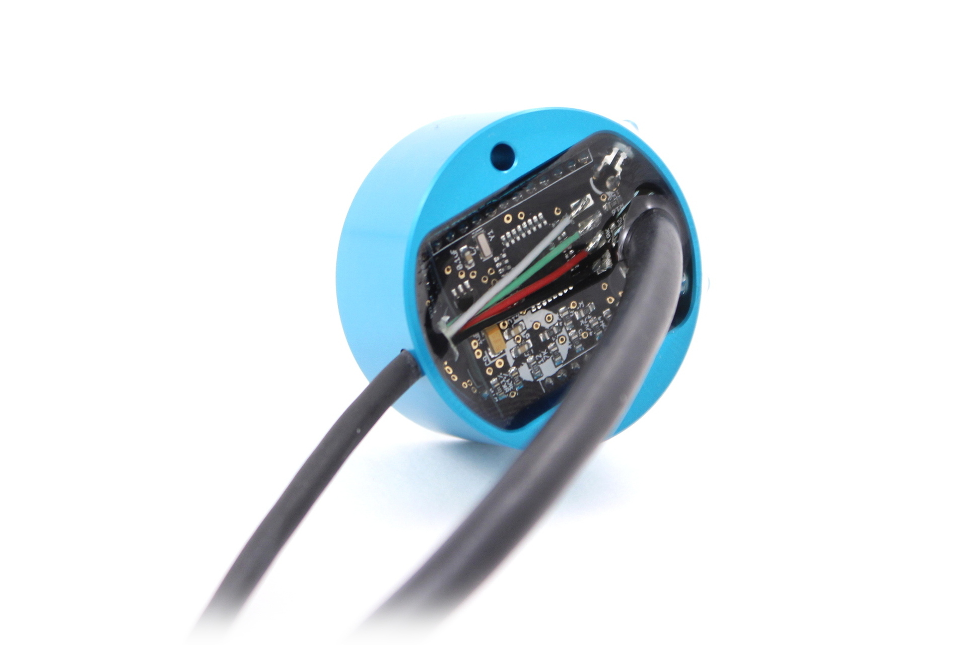
BlueESC Rev1 Prototype

The BlueESC is a simple, open-source electronic speed controller for three-phase brushless motors. It is designed to run the SimonK firmware on an Atmega8 microcontroller.

The hardware is licensed under GPLv3. It was inspired by and draws from other open-source ESC projects including AfroESC, WiiESC, and others. We owe a big thanks to everyone who has shared their open-source ESC designs and firmware.

We also thank Bernhard Konze and SimonK for the tgy firmware. Please see the firmware license at the top of tgy.asm. The firmware configuration files for the BlueESC are maintained in our fork of the tgy project.

##Features

  • Atmega8 microcontroller
  • PWM and I2C signal interfaces
  • 5-22 volt input (2-5s lipo)
  • Reprogrammable via PWM pin using bootloader (usblinker)
  • Status and warning LED indicators
  • Sensors for voltage, current, temperature, and RPM
  • No battery-eliminator-circuit (BEC)
  • N-Channel MOSFETs

##Current Generation: Rev. 5-8

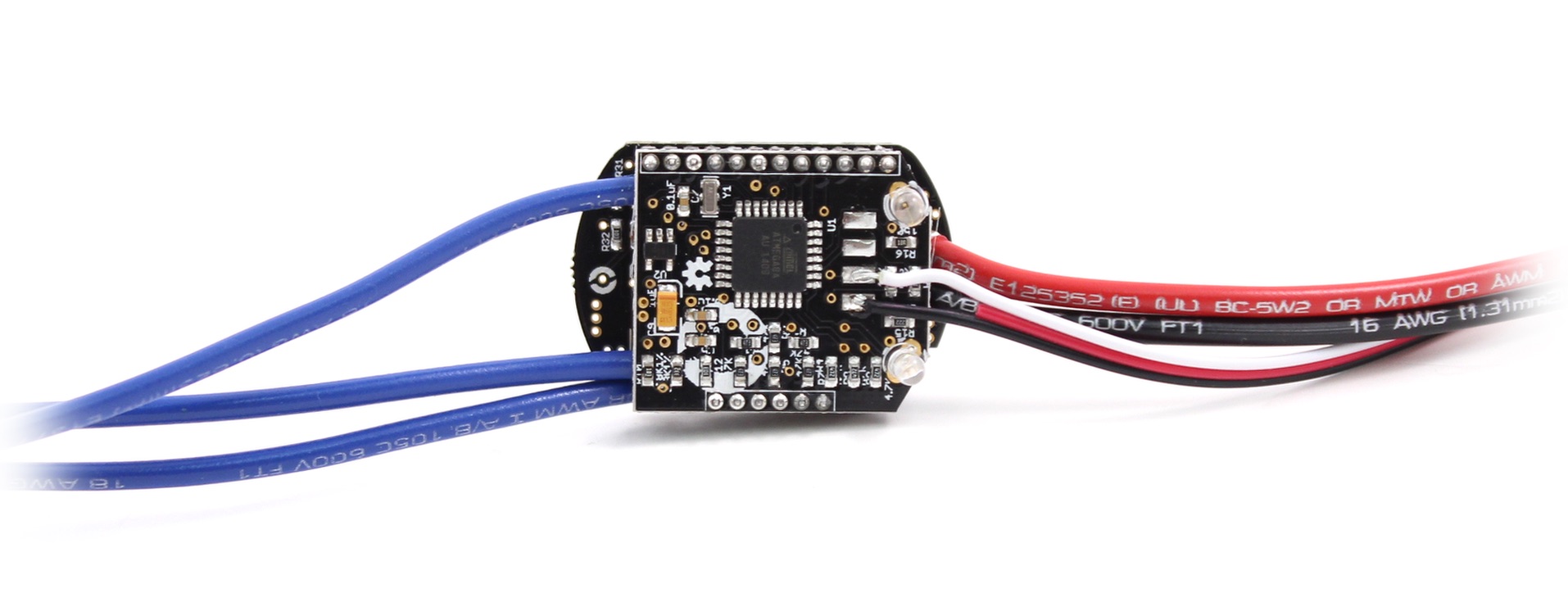
The current major revision is designed to work with the BlueRobotics T100 Thruster. It is highly compact and is potted in an aluminum enclosure that acts as a heat sink. The board is built with two 2-layer boards, one for the power electronics and one for logic. The boards are connected by headers. This allows components to be placed on three sides, simplifies design, and minimizes cost.

BlueESC Rev5 Board

###Features

  • Hall effect current sense IC (ACS711EX)
  • Thermistor temperature sensor (10K)

###Specifications

  • 6-22 volt input
  • 25 amps continuous current (air)
  • 35+ amps continuous current (water)
  • 400 uF decoupling capacitance
  • Enclosure diameter: 40 mm (1.58")
  • Enclosure length: 18.5 mm (0.73")

###Design Files

Schematic: BlueESC.pdf

See repository for up-to-date EagleCAD schematic and board layout.

##Firmware Compilation

The BlueESC uses the tgy firmware located in the BlueRobotics fork.

Mac: (Uses Homebrew)

brew update
brew install avra
make blueesc.hex

##Initial Firmware Flashing

The BlueESC can be flashed using any AVR ISP programmer.

avrdude -c [programmer] -p m8 -U flash:w:blueesc.hex:i 

The fuses should be set per the instructions in the tgy instructions.

avrdude -c [programmer] -p m8 -U lfuse:w:0x3f:m -U hfuse:w:0xca:m

The Rev5 version of the board does not include an ISP header or pads. The microcontroller must be flashed with a special tool that connects directly to the microcontroller pins. Make sure that the board is powered when programming.

##Firmware Flashing Through Bootloader

Once the ESC has had the firmware (including bootloader) flashed the first time, it can be reprogrammed subsequently through the PWM input pin using a programmer like the Turnigy USB Linker. This can be done through the Makefile in the tgy project as follows.

make program_tgy_blueesc

It can also be done with avrdude and the compiled hex files as follows.

avrdude -c stk500v2 -b 19200 -P [programmer port] -p m8 -U flash:w:blueesc.hex:i

##I2C Commands and Address

Please also see our Arduino library for I2C ESC control.

The I2C message format allows speed and direction to be set and voltage, current, rpm, temperature, and status to be requested.

###Speed Command (Register 0x00-0x01)

  • cmd: Command, sent as int16_t. Full range, negative for reverse, positive for forward.
    • Forward: 0 to 32767
    • Reverse: 0 to -32767

####Bytes

  • Byte 0: throttle_h
  • Byte 1: throttle_l

###Sensor Data (Register 0x02-0x0A)

  • pulse_count: Commutation pulses since last request. Sent as uint16_t.
    • Calculate rpm with pulse_count/dt*60/motor_pole_count
  • voltage: ADC measurement scaled to 16 bits
    • Calculate voltage with voltage/2016
  • temperature: ADC measurement scaled to 16 bits
    • Calculate temperature with the Steinhart equation
  • current: ADC measurement scaled to 16 bits
    • Calculate current with (current-32767)/891

####Bytes

  • Byte 0: pulse_count_h
  • Byte 1: pulse_count_l
  • Byte 2: voltage_h
  • Byte 3: voltage_l
  • Byte 4: temperature_h
  • Byte 5: temperature_l
  • Byte 6: current_h
  • Byte 7: current_l
  • Byte 8: 0xab (identifier to check if ESC is alive)

##Releases

v1.0 - Rev5. Currently shipping.

v1.1 - Rev6. Added PWM pull-down resistor and low pass filter for current sense. Switched to SMT LEDs. No changes to Power Board.

##Video

I2C Demonstration:

I2C Demonstration of BlueESC

Testing of Final Prototype:

Final Prototype of BlueESC

Testing of First Prototype:

First Test of BlueESC

blueesc's People

Contributors

rjehangir avatar

Stargazers

 avatar  avatar  avatar  avatar  avatar  avatar  avatar  avatar  avatar  avatar  avatar  avatar  avatar  avatar  avatar  avatar  avatar  avatar  avatar  avatar  avatar  avatar  avatar  avatar  avatar  avatar  avatar  avatar  avatar  avatar  avatar  avatar  avatar  avatar  avatar  avatar  avatar  avatar  avatar  avatar  avatar  avatar  avatar  avatar  avatar  avatar  avatar  avatar  avatar  avatar  avatar  avatar  avatar  avatar  avatar  avatar  avatar  avatar  avatar  avatar  avatar  avatar  avatar  avatar  avatar  avatar  avatar  avatar  avatar  avatar  avatar  avatar  avatar  avatar  avatar  avatar  avatar  avatar  avatar  avatar  avatar  avatar  avatar  avatar  avatar  avatar  avatar  avatar  avatar  avatar  avatar  avatar  avatar  avatar  avatar  avatar  avatar  avatar  avatar  avatar

Watchers

 avatar  avatar  avatar  avatar  avatar  avatar  avatar  avatar  avatar  avatar  avatar  avatar  avatar  avatar  avatar  avatar  avatar  avatar  avatar  avatar  avatar  avatar  avatar  avatar  avatar

blueesc's Issues

Low pass current sensor

The current sensor bandwidth is too high causing slow measurements to require a large software low-pass filter for accuracy. A hardware low pass should be added to resolve this.

Wrong RC time for the turn on of the upper FET in file "design-notes.md"

Hello. I was looking for an ingenious design which would me allow to ditch the gate drivers I use, hence looked at the schematic in https://github.com/bluerobotics/BlueESC/raw/master/BlueESC/BlueESC.pdf
But quickly realized that it will not perform on a par with the gate drivers (at least for the high side NMOSFETs).
The upper FETs are N-channel. They turn on with positive voltage on the gate relative to the source.
Watching the schematic in the https://github.com/bluerobotics/BlueESC/raw/master/BlueESC/BlueESC.pdf you can see that the upper FETs can get positive voltage on their gates from the high side of the capacitors via 100 Ω plus 2.2 kΩ resistors when the NPN transistors are OFF. This mean that the total resistance on this path is 2.3 kΩ, so the turn on RC constant is 10-20 times longer. E.t. instead of 100 nS, it goes at least to 1000 nS. This should lead to more heat generated by the upper FETs (if the charging pumps work as intended and supply higher than Vcc voltage to turn on the upper FETs). You should use either more sophisticated push-pull high side gate driver or use an IC gate driver (which of course will make the BOM with higher cost).

Rev1 high-side driver is for P-channel, not N-channel FETs

Hi Rusty:

I took a peek at the design you used for the Rev1 version of the BlueESC. The driver configuration you are using seems to be for a P-channel high-side switch, yet the schematic shows a N-channel high-side switch. I can't see how you're going to get a fully-enhanced high-side transistor with this configuration, leading to poor efficiency and overheating of the high-side transistor.

-Walt Holm

PWM signal pull down

Add a weak pull down to the PWM line so that it doesn't have to be grounded for I2C to work properly.

BlueESC Control Logic I2C

The manual doesn't explain what the red and blue LED's indicate on the integrated BlueESC. Also what does it mean when it beeps every few seconds?

I am able to read I2C data from the BlueESC but am unable to get prop spinning when writing I2C. Do you have any debug suggestions? Do you have to use PWM stop signal to activate motor, prior to being able to use I2C? I assume not? Do you have some I2C Python SBUS examples you could post to make sure I'm using your desired conventions? Thanks
[email protected]

modular ESC

Hi, sorry to open ticket for my question , actually I intend to made modular ESC in way that controller + gate driver is separated from Mosfets pcb , hence I could increase module ampere by adding parallel Mosfet in the Mosfets pcb, I really appreciated to have your advise or if you know open HW/SW sources let me know

Recommend Projects

  • React photo React

    A declarative, efficient, and flexible JavaScript library for building user interfaces.

  • Vue.js photo Vue.js

    🖖 Vue.js is a progressive, incrementally-adoptable JavaScript framework for building UI on the web.

  • Typescript photo Typescript

    TypeScript is a superset of JavaScript that compiles to clean JavaScript output.

  • TensorFlow photo TensorFlow

    An Open Source Machine Learning Framework for Everyone

  • Django photo Django

    The Web framework for perfectionists with deadlines.

  • D3 photo D3

    Bring data to life with SVG, Canvas and HTML. 📊📈🎉

Recommend Topics

  • javascript

    JavaScript (JS) is a lightweight interpreted programming language with first-class functions.

  • web

    Some thing interesting about web. New door for the world.

  • server

    A server is a program made to process requests and deliver data to clients.

  • Machine learning

    Machine learning is a way of modeling and interpreting data that allows a piece of software to respond intelligently.

  • Game

    Some thing interesting about game, make everyone happy.

Recommend Org

  • Facebook photo Facebook

    We are working to build community through open source technology. NB: members must have two-factor auth.

  • Microsoft photo Microsoft

    Open source projects and samples from Microsoft.

  • Google photo Google

    Google ❤️ Open Source for everyone.

  • D3 photo D3

    Data-Driven Documents codes.