gissio / radpro Goto Github PK
View Code? Open in Web Editor NEWCustom firmware for Geiger counters/radiation meters (FS2011, Bosean FS-600, FS-1000, FS-5000, FNIRSI GC-01)
License: MIT License
Custom firmware for Geiger counters/radiation meters (FS2011, Bosean FS-600, FS-1000, FS-5000, FNIRSI GC-01)
License: MIT License


I have 3 devices.
Fnirsi GC-1 with WCH, that i just updated to 2.0rc5 with STLink.
Another GC-1 that I updated with the bootloader drive.
And a Bosean FS-5000 where I get the error below.
(Pinout is different than GC-1, but I rearranged the pins.)
Any ideas?
Backing up old firmware image...
xPack Open On-Chip Debugger 0.12.0+dev-01557-gdd1758272-dirty (2024-04-02-07:27)
Licensed under GNU GPL v2
For bug reports, read
http://openocd.org/doc/doxygen/bugs.html
Info : auto-selecting first available session transport "hla_swd". To override use 'transport select '.
Info : The selected transport took over low-level target control. The results might differ compared to plain JTAG/SWD
Info : clock speed 500 kHz
Info : STLINK V2J39S7 (API v2) VID:PID 0483:3748
Info : Target voltage: 3.229005
Error: init mode failed (unable to connect to the target)
Flashing new firmware image...
xPack Open On-Chip Debugger 0.12.0+dev-01557-gdd1758272-dirty (2024-04-02-07:27)
Licensed under GNU GPL v2
For bug reports, read
http://openocd.org/doc/doxygen/bugs.html
Info : auto-selecting first available session transport "hla_swd". To override use 'transport select '.
Info : The selected transport took over low-level target control. The results might differ compared to plain JTAG/SWD
Info : clock speed 500 kHz
Info : STLINK V2J39S7 (API v2) VID:PID 0483:3748
Info : Target voltage: 3.238497
Error: init mode failed (unable to connect to the target)
Hey guys, I have a problem, I bought a FNIRSI GC-01 on latest firmware v1.6-2, with APM32F103RBT6 (Geehy) microcontroller. Picture of motherboard included.
I wanted to try the radpro firmware, but I am stuck on accessing the drive. If I follow the install instructions, I turn off the device,
plug a USB C cable (verified data transfer cable) into the device and pres the power button, the device just boots up and starts working.
No drive shows up in My computer, no device connected beep is heard. The machine is a Lenovo Legion 5i laptop running latest Windows 11. I am out of ideas, I tried holding down right button while plugging the USB, I tried disconnecting the internal battery and removien the backup battery, nothing works.... Please help me.... What am I doing wrong ? What could I try ?

Do you still plan to support FS-600 and if so, when in time?
I just got a FS-600 and it bugs me that there is a USB-C port but the device lacks capability of reporting anything through it.
If you need pictures of the internals, please let me know.
Installation of rc5 was straight forward, and code is running on GeigerLog.
Most interesting to me is the feature allowing PWM setting. But has anything been changed there? It seems I am getting different voltages - much higher - than with the same settings on rc3?
I have noticed very low background radiation levels with this tube. In your description, I've found that you are using 64.8 cpm/µSv/h (9,5 cpm/mR/h) for both J613 and J614, but on the J614 datasheet I found online, they stated 5 cpm/mR/h, which is ~34,2 cpm/µSv/h. So I've set 33,9 cpm/µSv/h, and now my long-time average readings are more or less on par, with my old RKSB-104.
Hi,
I received a FS2011 from aliexpress and the board revision seems to be slightly different (e.g. buzzer, tube location + some components), plus the cpu is different
GD32F103
C8T6
CDU1310
DJ2216
GigaDevice
ARM
After programming, no display, no sounds, buttons don't seem to do anything. After flashing the backup two or three times it is working again.


Not really experienced with ARM CPUs so some hints on where/how I can find the correct board definitions would be very beneficial, otherwise I will try on my own, probably in the next days.
(tried to flash some of the later versions but none seems to work)
in flashtool.sh are some syntax errors - at least for MacOS:
./flashtool.sh: line 13: [: missing ]' ./flashtool.sh: line 16: [: missing ]'
There are missing blanks after "x86_64" and "arm64".
After correction everything is working for me.
Hello
Your RadPro software mentions that it should support a NR-950 geiger counter.
Does it extend to other NR series devices?
I'm most interested about NR-750 radiation monitor, as this is the one I planned on reprogramming.
This model uses a MSP430F147 microcontroller.
If the software is compatible, will I be able to use an ST-link for programming, like with FS-2011?
Finally, could You help me with locating reprogramming pins on the board, if I provide detailed photos of it?
Thank you, and wish you luck with this project!
The temperature shows >300C and the battery icon shows "charging" all the time.

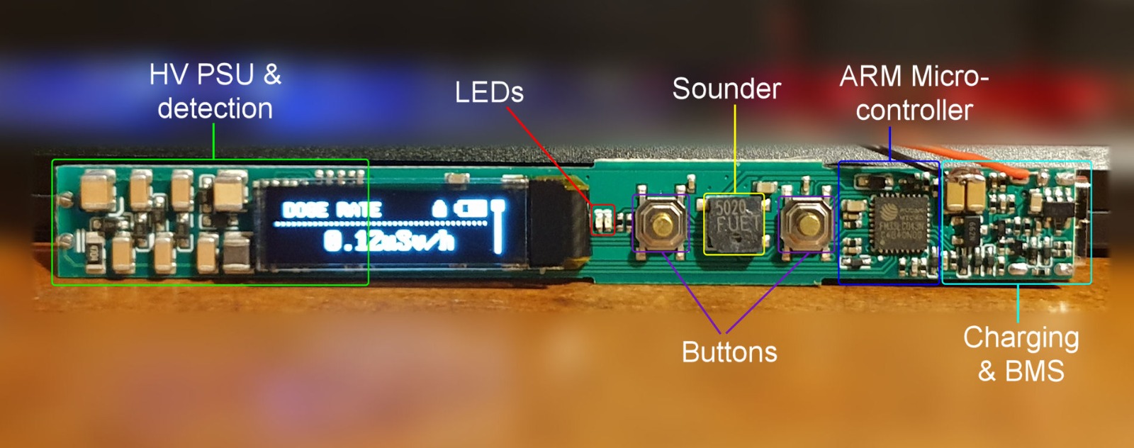
This is a cheap little pen-like radiation detector/dosimeter from China that apparently could benefit from a lot of firmware improvements:
Here is a nice an thorough review of it.
MCU: ARM Cortex-M0 FM33LC043N MCU from Fudan Micro
Sensor: HH614 GM Tube
Battery: 150mAh LiPo cell - 50h promised
PCB layout [from radmon.org forum]
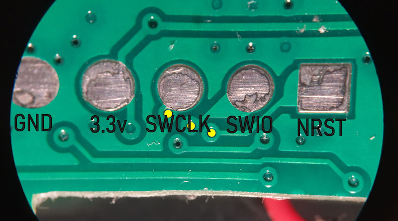
SWD pins layout under the battery tape [from radmon.org forum]
Originally posted by drehugo February 27, 2024
I tried to copy the new firmware over to my counter and received an insufficient memory error of needing another 16 kb. Do you know of anyway to free up more ram?
Hello sir, as in the title. The GC-01 with apm32f103rb with latest firmware has a battery life of about 20 hours maximum (screen off!). Also, and it may hint to other issues ??? - turning on or off the unit whilst charging causes a blank screen needing a hard reset or reload of firmware. Please also note the charging voltage is far too high for the battery - reaching 4.65V
Thank you. Joe
To get st-flash.exe to work (Windows 11) I needed to download and install the drivers from https://www.st.com/en/development-tools/stsw-link009.html#get-software
st-info --probe
2023-09-18T14:19:03 ERROR usb.c: Failed to open USB device 0x0483:0x3748, libusb error: -12)
Found 0 stlink programmers
after installing
st-info --probe
Found 1 stlink programmers
  version:    V2J29S7
  serial:     16004A002933353739303541
  flash:      131072 (pagesize: 2048)
  sram:       36864
  chipid:     0x0460
  descr:      G070/G071/G081
Originally posted by alfmck March 31, 2024
After flashed radpro I noticed that when my GC-01 is in measurement state, time by time it enters in MODE state.
I checked the signals on buttons wires with oscilloscope and saw that the short pulses to ground induces from high voltage generator. The biggest of them were on MODE button wire. It looks that the button state scanning algorithm sometimes detects these pulses as the MODE button was pressed. My GC-01 has a H614 tube soldered nearby this button. Maybe there was defect in pin9 of CH32F103R8T6 that after trying physically filter that pulse, pin9 on MC became faulty. So, I'm going to reprogram radpro, making button UP to fulfill MODE button function. Thank Gissio that You supplied distributives.
I used the 'data logging' function with 60 minutes today. I noticed that the f-nirsi ran down the battery at least 50% faster than without the function.
Presumably only a short text line or file with the values should be made every 60 minutes, right?
I have now deactivated the function and will check the time without 'data logging' again after an hour of charging.
I flashed 2.0beta11 onto two YT-203B with GD32F150 MCUs. The device temperature shown on the statistics screen for both units fluctuates between 320 to 323 °C at room temperate (about 19°C).
quando hai reversato lo schema, a mio parere, il duplicatore di tensione e' sbagliato
il duplicatore dovrebbe avere i consensatori in serie e i diodi che vanno da +/-
https://www.lucianomarroccu.com/un-p%C3%B2-di-teoria/moltiplicatore-di-tensione/
il primo che ho trovato
p.s.
stavo pensando ma se con il https://www.google.com/search?q=esp32+WT32-SC01, gli facessi un geiger con il tuo software
avremmo usb dati, sd, wifi webserver o bluetooth,
(costa meno un geiger gia fatto del solo tubo)
Battery icon stays the same not depending the battary charge percent or charging process.
It shows fully gray battery with gray flash icon on it.
hi, congratulations on your work. I have a big problem, I bought the cg-01 from China and it arrived with the 613-614 tube, it doesn't write. I ordered the j321 tube to change it. My mcu is a


 . I've tried every way and I can't get it to show on the computer. can you help me thanks. are you a radio amateur? I'm YO8SAF Aldo
i use google transate sorry but I use google translator, because my English is not very good, sorry
cmd shell was still open:

`c:\temp\ft>flash-fs2011-gd32f150c8.bat
Backing up old firmware image...
xPack Open On-Chip Debugger 0.12.0+dev-01557-gdd1758272-dirty (2024-04-02-07:27)
Licensed under GNU GPL v2
For bug reports, read
http://openocd.org/doc/doxygen/bugs.html
0
Info : auto-selecting first available session transport "hla_swd". To override use 'transport select '.
Info : The selected transport took over low-level target control. The results might differ compared to plain JTAG/SWD
Info : clock speed 1000 kHz
Info : STLINK V2J37S7 (API v2) VID:PID 0483:3748
Info : Target voltage: 3.221466
Info : [stm32f0x.cpu] Cortex-M3 r2p1 processor detected
Info : [stm32f0x.cpu] target has 6 breakpoints, 4 watchpoints
Info : [stm32f0x.cpu] Examination succeed
Info : starting gdb server for stm32f0x.cpu on 3333
Info : Listening on port 3333 for gdb connections
Info : Unable to match requested speed 1000 kHz, using 950 kHz
Info : Unable to match requested speed 1000 kHz, using 950 kHz
[stm32f0x.cpu] halted due to debug-request, current mode: Thread
xPSR: 0x01000000 pc: 0xfffffffe msp: 0xfffffffc
Flashing new firmware image...
xPack Open On-Chip Debugger 0.12.0+dev-01557-gdd1758272-dirty (2024-04-02-07:27)
Licensed under GNU GPL v2
For bug reports, read
http://openocd.org/doc/doxygen/bugs.html
0
Info : auto-selecting first available session transport "hla_swd". To override use 'transport select '.
Info : The selected transport took over low-level target control. The results might differ compared to plain JTAG/SWD
Info : clock speed 1000 kHz
Info : STLINK V2J37S7 (API v2) VID:PID 0483:3748
Info : Target voltage: 3.221466
Info : [stm32f0x.cpu] Cortex-M3 r2p1 processor detected
Info : [stm32f0x.cpu] target has 6 breakpoints, 4 watchpoints
Info : [stm32f0x.cpu] Examination succeed
Info : starting gdb server for stm32f0x.cpu on 3333
Info : Listening on port 3333 for gdb connections
Info : Unable to match requested speed 1000 kHz, using 950 kHz
Info : Unable to match requested speed 1000 kHz, using 950 kHz
[stm32f0x.cpu] halted due to debug-request, current mode: Thread
xPSR: 0x01000000 pc: 0xfffffffe msp: 0xfffffffc
Info : device id = 0x13030410
Info : flash size = 64 KiB
Info : Unable to match requested speed 1000 kHz, using 950 kHz
Info : Unable to match requested speed 1000 kHz, using 950 kHz
[stm32f0x.cpu] halted due to debug-request, current mode: Thread
xPSR: 0x01000000 pc: 0xfffffffe msp: 0xfffffffc
Info : Unable to match requested speed 8000 kHz, using 4000 kHz
Info : Unable to match requested speed 8000 kHz, using 4000 kHz
** Programming Started **
Error: Error setting register xpsr
Error: failed to get read pointer
Error: timed out while waiting for target halted
[stm32f0x.cpu] halted due to debug-request, current mode: Handler HardFault
xPSR: 0x01000003 pc: 0xfffffffe msp: 0xffffffd8
Error: error waiting for target flash write algorithm
Error: error writing to flash at address 0x08000000 at offset 0x00000000
embedded:startup.tcl:1689: Error: ** Programming Failed **
in procedure 'program'
in procedure 'program_error' called at file "embedded:startup.tcl", line 1754
at file "embedded:startup.tcl", line 1689
Done.
Drücken Sie eine beliebige Taste . . .
`
i have rewrite a cpu firmware ad have used https://www.amazon.it/dp/B07H9XV2W2/ to upload firmware in jtag, check wire connection from to gg-01, the cpu is ch32f103r8 che st v2 read the cpu, and succefull write, the display remain blank
i use a stm32 official software in windows to write a cpu.
Ok Guys, here is the foolproff to get the FW loaded. Works everytime.....
After you connect your GC-01 via usb to your PC you "hold down" the power switch. As long as you hold it down, you will see the disk appear on your PC. So hold it down, then drag the repo onto your disk icon. Release the power button when you see the GC-01 booting. Takes only a few seconds. And it doesn't matter the USB protocol. It just works.
Originally posted by @jackhen in #24 (comment)
Everytime I turn the device on, it is in the Hold mode of Instantaneous screen. It does not matter if I previously turned it off in Hold mode or not. While turning it on, I release the center OK key as soon as the LED turns off and Rad Pro splashscreen appears.
Installed Rad Pro on GC-01's with a CH32F103R8T6 processor (WCH) radpro-fnirsi-gc01-ch32f103r8-2.0rc4.bin.
All work beautifully on the device, thank you! I would like to use the serial interface to read the data from the device but have some issues on Linux with enumerating the serial port over USB correctly.
May 25 22:12:49 b54583.lan kernel: usb 3-5.3.2.3: Device not responding to setup address.
May 25 22:12:49 b54583.lan kernel: usb 3-5.3.2.3: Device not responding to setup address.
May 25 22:12:49 b54583.lan kernel: usb 3-5.3.2.3: device not accepting address 88, error -71
May 25 22:12:49 b54583.lan kernel: usb 3-5.3.2.3: WARN: invalid context state for evaluate context command.
May 25 22:12:49 b54583.lan kernel: usb 3-5.3.2-port3: unable to enumerate USB device
May 25 22:12:49 b54583.lan kernel: usb 3-10: reset full-speed USB device number 3 using xhci_hcd
May 25 22:12:49 b54583.lan kernel: usb 3-10: reset full-speed USB device number 3 using xhci_hcd
May 25 22:21:49 b54583.lan kernel: perf: interrupt took too long (2508 > 2500), lowering kernel.perf_event_max_sample_rate to 79000
May 25 22:22:20 b54583.lan kernel: usb 3-10: reset full-speed USB device number 3 using xhci_hcd
May 25 22:22:20 b54583.lan kernel: usb 3-10: reset full-speed USB device number 3 using xhci_hcd
May 25 22:22:31 b54583.lan kernel: usb 3-5.3.2.3: new full-speed USB device number 89 using xhci_hcd
May 25 22:22:31 b54583.lan kernel: usb 3-5.3.2.3: device descriptor read/64, error -32
May 25 22:22:31 b54583.lan kernel: usb 3-5.3.2.3: device descriptor read/64, error -32
May 25 22:22:32 b54583.lan kernel: usb 3-5.3.2.3: new full-speed USB device number 90 using xhci_hcd
May 25 22:22:32 b54583.lan kernel: usb 3-5.3.2.3: device descriptor read/64, error -32
May 25 22:22:32 b54583.lan kernel: usb 3-5.3.2.3: device descriptor read/64, error -32
May 25 22:22:32 b54583.lan kernel: usb 3-5.3.2-port3: attempt power cycle
May 25 22:22:34 b54583.lan kernel: usb 3-5.3.2.3: new full-speed USB device number 91 using xhci_hcd
May 25 22:22:34 b54583.lan kernel: usb 3-5.3.2.3: Device not responding to setup address.
May 25 22:22:34 b54583.lan kernel: usb 3-5.3.2.3: Device not responding to setup address.
May 25 22:22:34 b54583.lan kernel: usb 3-5.3.2.3: device not accepting address 91, error -71
May 25 22:22:34 b54583.lan kernel: usb 3-5.3.2.3: WARN: invalid context state for evaluate context command.
May 25 22:22:34 b54583.lan kernel: usb 3-5.3.2.3: new full-speed USB device number 92 using xhci_hcd
May 25 22:22:34 b54583.lan kernel: usb 3-5.3.2.3: Device not responding to setup address.
May 25 22:22:35 b54583.lan kernel: usb 3-5.3.2.3: Device not responding to setup address.
May 25 22:22:35 b54583.lan kernel: usb 3-5.3.2.3: device not accepting address 92, error -71
May 25 22:22:35 b54583.lan kernel: usb 3-5.3.2.3: WARN: invalid context state for evaluate context command.
May 25 22:22:35 b54583.lan kernel: usb 3-5.3.2-port3: unable to enumerate USB device
May 25 22:24:17 b54583.lan kernel: usb 3-5.3.2.3: new full-speed USB device number 93 using xhci_hcd
May 25 22:24:17 b54583.lan kernel: usb 3-5.3.2.3: device descriptor read/64, error -32
May 25 22:24:17 b54583.lan kernel: usb 3-5.3.2.3: device descriptor read/64, error -32
May 25 22:24:17 b54583.lan kernel: usb 3-5.3.2.3: new full-speed USB device number 94 using xhci_hcd
May 25 22:24:17 b54583.lan kernel: usb 3-5.3.2.3: device descriptor read/64, error -32
May 25 22:24:18 b54583.lan kernel: usb 3-5.3.2.3: device descriptor read/64, error -32
May 25 22:24:18 b54583.lan kernel: usb 3-5.3.2-port3: attempt power cycle
May 25 22:24:20 b54583.lan kernel: usb 3-5.3.2.3: new full-speed USB device number 95 using xhci_hcd
May 25 22:24:20 b54583.lan kernel: usb 3-5.3.2.3: Device not responding to setup address.
May 25 22:24:20 b54583.lan kernel: usb 3-5.3.2.3: Device not responding to setup address.
May 25 22:24:20 b54583.lan kernel: usb 3-5.3.2.3: device not accepting address 95, error -71
May 25 22:24:20 b54583.lan kernel: usb 3-5.3.2.3: WARN: invalid context state for evaluate context command.
May 25 22:24:20 b54583.lan kernel: usb 3-5.3.2.3: new full-speed USB device number 96 using xhci_hcd
May 25 22:24:20 b54583.lan kernel: usb 3-5.3.2.3: Device not responding to setup address.
May 25 22:24:20 b54583.lan kernel: usb 3-5.3.2.3: Device not responding to setup address.
May 25 22:24:20 b54583.lan kernel: usb 3-5.3.2.3: device not accepting address 96, error -71
May 25 22:24:20 b54583.lan kernel: usb 3-5.3.2.3: WARN: invalid context state for evaluate context command.
May 25 22:24:20 b54583.lan kernel: usb 3-5.3.2-port3: unable to enumerate USB device
May 25 22:30:03 b54583.lan kernel: usb 3-10: reset full-speed USB device number 3 using xhci_hcd
May 25 22:30:03 b54583.lan kernel: usb 3-10: reset full-speed USB device number 3 using xhci_hcd
Mass storage is enumerated correctly:
May 25 22:58:07 b54583.lan kernel: usb 3-5.3.2.3: new full-speed USB device number 97 using xhci_hcd
May 25 22:58:07 b54583.lan kernel: usb 3-5.3.2.3: New USB device found, idVendor=0483, idProduct=002a, bcdDevice= 2.00
May 25 22:58:07 b54583.lan kernel: usb 3-5.3.2.3: New USB device strings: Mfr=1, Product=2, SerialNumber=3
May 25 22:58:07 b54583.lan kernel: usb 3-5.3.2.3: Product: AIR01
May 25 22:58:07 b54583.lan kernel: usb 3-5.3.2.3: Manufacturer: FNIRSI
May 25 22:58:07 b54583.lan kernel: [44B blob data]
May 25 22:58:07 b54583.lan kernel: usb-storage 3-5.3.2.3:1.0: USB Mass Storage device detected
May 25 22:58:07 b54583.lan kernel: scsi host1: usb-storage 3-5.3.2.3:1.0
May 25 22:58:08 b54583.lan kernel: scsi 1:0:0:0: Direct-Access     AIR      DETECTION 1.0         PQ: 0 ANSI: 2
May 25 22:58:08 b54583.lan kernel: sd 1:0:0:0: Attached scsi generic sg0 type 0
May 25 22:58:08 b54583.lan kernel: sd 1:0:0:0: [sdb] 51200 2048-byte logical blocks: (105 MB/100 MiB)
May 25 22:58:08 b54583.lan kernel: sd 1:0:0:0: [sdb] Write Protect is off
May 25 22:58:08 b54583.lan kernel: sd 1:0:0:0: [sdb] Mode Sense: 03 00 00 00
May 25 22:58:08 b54583.lan kernel: sd 1:0:0:0: [sdb] No Caching mode page found
May 25 22:58:08 b54583.lan kernel: sd 1:0:0:0: [sdb] Assuming drive cache: write through
May 25 22:58:08 b54583.lan kernel: sd 1:0:0:0: [sdb] Attached SCSI removable disk
Is USB-C to serial bridge supported on GC-01 with WCH MCU?
I'm trying to flash an fs-5000. i have tried 2 separate counters with the same results. I can connect to it using the st-link utility and I included an image of that. but if i try to do anything with the utility it says device has shut down.
Backing up old firmware image...
xPack Open On-Chip Debugger 0.12.0+dev-01557-gdd1758272-dirty (2024-04-02-07:27)
Licensed under GNU GPL v2
For bug reports, read
http://openocd.org/doc/doxygen/bugs.html
Info : auto-selecting first available session transport "hla_swd". To override use 'transport select '.
Info : The selected transport took over low-level target control. The results might differ compared to plain JTAG/SWD
Info : clock speed 500 kHz
Info : STLINK V2J37S7 (API v2) VID:PID 0483:3748
Info : Target voltage: 1.566316
Error: init mode failed (unable to connect to the target)
Flashing new firmware image...
xPack Open On-Chip Debugger 0.12.0+dev-01557-gdd1758272-dirty (2024-04-02-07:27)
Licensed under GNU GPL v2
For bug reports, read
http://openocd.org/doc/doxygen/bugs.html
Info : auto-selecting first available session transport "hla_swd". To override use 'transport select '.
Info : The selected transport took over low-level target control. The results might differ compared to plain JTAG/SWD
Info : clock speed 500 kHz
Info : STLINK V2J37S7 (API v2) VID:PID 0483:3748
Info : Target voltage: 1.564737
Error: init mode failed (unable to connect to the target)
Done.
Press any key to continue . .

Just received a FS2011 from amazon (6/27) and the board revision is the same as your picture, Z27809 but the CPU different:
GD32F150
C8T6
CEHH213
AJ2151
GigaDevice
ARM
After programming, no display, no sounds, buttons don't seem to do anything. Have not had time to recompile for the different processor yet.
Pictures to follow later...
Question: what should be the default display theme for the FNIRSI GC-01?
FNIRSI GC-01_V0.2 with a CH32F103R8T6 (WCH) processor. Unable to flash with rc4 or rc5.
Initially the device was showing up as mass storage, but was not reacting after successfully copy of the binary. I did a few sequential test and variations:
ok/power device shows as mass storage GC01 BOOT, with single empty Readme.txt, dragging and dropping radpro-fnirsi-gc01-ch32f103r8-2.0rc4.bin file copied successfully but device did not reboot.ok/power device shows as mass storage GC01 BOOT, with single empty Readme.txt, dragging and dropping radpro-fnirsi-gc01-ch32f103r8-2.0rc4.bin file copied successfully but device did not reboot. After releasing button mass storage disconnects but the firmware was not flashed.ok/power device shows as mass storage GC01 BOOT, with single empty Readme.txt, holding right arrow[cogwheel] and key dragging and dropping radpro-fnirsi-gc01-ch32f103r8-2.0rc4.bin file copied successfully but device did not reboot, releasing the arrow there was no change.fnirsi-gc01-ch32f103r8t6-v0.3.bin and fnirsi-gc01-ch32f103r8t6-v1.5.bin no response.At that stage the original firmware was still fully functional.
Then I moved to the alternative flash instructions. As I did no have ST-LINK I used my J-LINK that supports SWD. Set-up and the JLink software recognised the chip.
I flashed the radpro-fnirsi-gc01-ch32f103r8-2.0rc4.bin it did flashed successfully but after that the device was not starting anymore, or showing as mass-storage device.
Unfortunately I did not save the original, before overriting it, not the only thing that still works is the bootloader, and the mass-storage is showing up as a drive, but cant power up.
I have tied flashing all binaries and test with each one, but no change from the above. Example log output from the J-LInk:
Opening data file [~/Downloads/fnirsi-gc01-ch32f103r8t6-bootloader.bin] ...
 - Data file opened successfully (16384 bytes, 1 range, CRC of data = 0x84FA8749, CRC of file = 0x84FA8749)
Connecting ...
 - Connecting via USB to probe/ programmer device 0
 - Probe/ Programmer firmware: J-Link ARM V8 compiled Nov 28 2014 13:44:46
 - Probe/ Programmer S/N: 788529158
 - Device "CS32F103C8" selected.
 - Target interface speed: 4000 kHz (Fixed)
 - VTarget = 3.319V
 - InitTarget() start
 - SWD selected. Executing JTAG -> SWD switching sequence.
 - DAP initialized successfully.
 - InitTarget() end - Took 19.0ms
 - Found SW-DP with ID 0x2BA01477
 - DPv0 detected
 - CoreSight SoC-400 or earlier
 - Scanning AP map to find all available APs
 - AP[1]: Stopped AP scan as end of AP map has been reached
 - AP[0]: AHB-AP (IDR: 0x24770011)
 - Iterating through AP map to find AHB-AP to use
 - AP[0]: Core found
 - AP[0]: AHB-AP ROM base: 0xE00FF000
 - CPUID register: 0x412FC231. Implementer code: 0x41 (ARM)
 - Found Cortex-M3 r2p1, Little endian.
 - FPUnit: 6 code (BP) slots and 2 literal slots
 - CoreSight components:
 - ROMTbl[0] @ E00FF000
 - [0][0]: E000E000 CID B105E00D PID 000BB000 SCS
 - [0][1]: E0001000 CID B105E00D PID 003BB002 DWT
 - [0][2]: E0002000 CID B105E00D PID 002BB003 FPB
 - [0][3]: E0000000 CID B105E00D PID 003BB001 ITM
 - [0][4]: E0040000 CID B105900D PID 003BB923 TPIU-Lite
 - Executing init sequence ...
  - Initialized successfully
 - Target interface speed: 4000 kHz (Fixed)
 - Found 1 JTAG device. Core ID: 0x2BA01477 (None)
 - Connected successfully
Auto programming target (16384 bytes, 1 range) ...
 - Checking if selected data fits into selected flash sectors.
 - Start of preparing flash programming
 - End of preparing flash programming
 - Start of determining dirty areas in flash cache
 - End of determining dirty areas
 - CPU speed could not be measured.
 - Start of erasing sectors
 - Blank checking 0x08000000 - 0x08003FFF
 - Erasing range 0x08000000 - 0x08003FFF ( 16 Sectors, 16 KB)
 - End of erasing sectors
 - Start of flash programming
 - Programming range 0x08000000 - 0x08003FFF ( 16 Sectors, 16 KB)
 - End of flash programming
 - Flash programming performed for 1 range (16384 bytes)
 - 0x8000000 - 0x8003FFF ( 16 Sectors, 16 KB)
 - Start of verifying flash
 - End of verifying flash
 - Start of restoring
 - End of restoring
 - Executing exit sequence ...
  - De-initialized successfully
 - Target erased, programmed and verified successfully - Completed after 23.415 sec
Any advice or help would be appreciated, I do not want to run the original firmware but radpro one instead, mainly as I want to be able to read the data form the sensor via USB. Some photos
It would be quite handy (and more robust for knowing which bit of info has been returned) if there was an API call like GET allInfo which could return something like
{"tubePulseCount": 35, "deviceId": "Bosean FS-1000;Rad Pro 2.0beta9;1414549528", "deviceTemperature": 16.6, "deviceTime": 1699699817, "tubeTime": 446, "tubeRate": 4.518, "tubeDutyCycle": 0.500,"tubeConversionFactor": 68.400,"tubeDeadTime": 0.0006695,"tubeDeadTimeCompensation": 0.0000000,"entropy": "8f46"}
also "deviceId": "Bosean FS-1000;Rad Pro 2.0beta9;1414549528" could be split as eg
"deviceName": "Bosean FS-1000", deviceSoftware:"Rad Pro 2.0beta9", "deviceId":"414549528
Setup: Haptic Pulses -> strong
After power on for the first pulses the motor runs weak. (half turn or so).
Later on, with more pulses it runs normal.
This behaviour is not always, after a short power off->power on cycle it runs normal from power on.

FS9000 Dosimeter I have on hand was bought during spring 2022 on AliExpress.
To my surprise, it doesn't have an ST ARM CPU, but a TI MSP430F147 MCU:
https://www.ti.com/product/MSP430F147
Also, it doesn't have a 4-pin XS1 header, but 10-pin J3 header instead.
I've unsoldered the BZ1 buzzer (because stock firmware is buggy, and signals even if alert conditions were not met).
But FT232 & mini-USB connectors were unpopulated.
I guess support for it is out of question, isn't it?


I've noticed that graph bar is not correctly displaying actual reading. Reading is 0,121uS/h while graph is almost at 0,5uS/h

Thank you for the great work with radpro!
However I suffer from issue with downloading data from fnirsi (both datalog, and in real time)
python tools/radpro-tool.py -p COM3 --no-sync-time --download-datalog moj-datalog.csv Downloading offline data...
Gives no error but moj-datalog.csv is empty, only the:
time,tubePulseCount are present, also:
python tools/radpro-tool.py -p "COM3" --log-rng odczyty.csv
Gives empty file. Of course logging option is enabled in the device.
Also sometimes, I encounter other strange behavior, for example:
python tools/radpro-tool.py -p COM3 --get-device-id
Error while setting device time.
Error while getting property "deviceId".
(base) PS E:\PROGRAMMING\radpro> python tools/radpro-tool.py -p COM3 --no-sync-time --download-datalog moj-datalog.csv
Downloading offline data...
Error while downloading data log.
What is the reason of this?
Hello.
No matter what I try on my FINRSI CH32F
The device boots up just after the flash and is running fine, but if I switch the device off then on again multiple time, at some point ( there is no pattern that I could determine ) the device stays stucked on "Radpro version" screen then blacks out. In that state, not even the power button works. It's in hanged state.
Edit: The device eventually goes back to life, but after a solid 30 seconds or so.
I had the impression it was stucked because at some point the boot process is much longer.
I have to reset then reflash to bring it back to life.
Never had a glitch with the stock firmware.
Any ideas?

Hi, super super cool project.
Is there any possibility of having support for the FNIRSI GC-01 ? It seems very similar to other devices already supported.
Ciao
Errors in description of GD-01 Flashtool:
The pins in my GD-01 (CH32F103) from left to right, are:
SWCLK
SWDIO
GND
+3.3V
Maybe the order changes from release to release :)
But it is written on the board, that's why its no problem for me.
Please write in description, that the ST-link dongle and the power USB has to be connected for a successful flashing.
Thanks for this great project
I tried the new 2.0 beta16 on a board revision KL7 820.403D. The display had all pixels set to black, no background light, text was only readable in a very steep angle. keyboard seems to fail also. Klicks were hearable, the LED was flashing also.
Back to 2.0beta10 everything worked again.
The docs: https://github.com/Gissio/radpro/blob/main/docs/manual.md#random-number-generator talk about using a radioactive source to speed things up, but it doesn't list any suggested length of time it should take under normal background radiation. Can you clarify what we would expect to see?
I ran the random password with full ASCII for quite a while and never saw any output?

There is a teardown on YT showing the same PCB just with a graphics display. https://www.youtube.com/watch?v=fNMOmk37HbM. Looks to me like another display, but the rest might be standard. Any chance?
No custom settings (units, avg. timer, rate&dose alarm, geiger tube,...) are kept after the device is restarted. Time is kept but not the timezone.
I have a BOSEAN FS-600 running RadPro version 2.0beta23
Otherwise, the software is absolutely awesome and actually makes the device usable (original firmware readings are mostly nonsense)
Hi, this looks very cool!
For the FS1000 do you think the direct logging to the computer would work with the built in USB socket?
radpro/platform.io/src/display.c
Line 949 in e57e4c5
Something like this instead?
strcatUInt32(buffer, (dateTime.hour % 12) ? (dateTime.hour % 12) : 12, 1);
The instructions mention files named like radpro-fs2011-\[MCU\]-install-x.y.z.bin, but the releases only have one file - radpro-fs2011-1.3.0-install.bin.
If you wish to report a problem with Rad Pro, post it in Issues.
If you wish to ask questions, make suggestions, or ask for help, post them in Discussions.
If you are not fluent in English, please post in your native language. It will make things easier for all of us.
I want to run a script on my PC that would email and SMS me data log of when the measurement goes +X%.
Is it possible to grab the readings or logs from the GC-01.
This is the one I got.
https://www.amazon.com/Geiger-Counter-Nuclear-Radiation-Detector/dp/B0BHH9X1WG/ref=sr_1_4?keywords=nuclear+radiation+detector&sr=8-4&ufe=app_do%3Aamzn1.fos.18ed3cb5-28d5-4975-8bc7-93deae8f9840
Also wanted to hook it up to my android phone to map rad levels while traveling on plane.
Thanks for the help.
Hello!
I have the device with ch32f103 processor. It shows the incorrect temperature: 9 °C when the environment is 28 °C.
Photos
Also my device resets the current date and time after rebooting. But the time zone is saved correctly. Perhaps it's my battery problem?
I've just released 2.0rc1 (release candidate 1) which should fix a power management issue on the FNIRSI GC-01: even though the device seemed to be turned off, it continued draining power.
Can somebody check that the GC-01 is not draining power when turned on, and then off?
Hey Ho,
My main Issue is, I have two different GC-01 (with the J321 and with J613) the readings of the two Device differ a lot.
The Device with the tiny tube (J613)? and original 1.62 Firmware I had a Reading of MIN-MAX 0.03-0.10μS/h while the J321 with the Original FW I got MIN-MAX 0.06-0.21μS/h over 10min.
With the RadPro FW I get MIN-MAX 0.022-0.130μS/h Avg 0.056μS/h while the J321 with original FW still sits at MIN-MAX 0.10-0.26μS/s Avg 0.12μS/h.
All of the Testing with the J613 was done with the HV-Profile set to Factory 2.
I have seen there are a bunch of different Conversion Factor presets.
I tried all of the 'J' so J305-J614, the J613 Profile is indeed the Closest to the J315 Values, but still misses ~x2-x4
Any reccomendation, or how to deal with the 'missing' counts?
Hi,
I'd like to help getting support for this relatively new Bosean FS-5000 Geiger counter.
Here are some specs:
MCU: ARM Cortex-M4 STM32L431RCT6 80 MHz, 64KB SRAM, 256KB Flash
Extra Flash: winbond 25q64jvsiq - 8 MB serial flash
USB to TTL: WCH 340EB27 (basically a CH340)
| Sensor | J321 Glass Geiger Tube |
| LCD screen | 2.4-inch TFT LCD H24C159 |
| Measurement range of dose rate | 0.01 uSv/h~50 mSwh |
| Dose measurement range | 0 uSv~1000Sv |
| Sensitivity | >1 CPS/uSv/h |
| Energy response | 48keV~1.5MeV |
| Relative error | <10%(1mSv/h) |
| Power supply | 3.7V rechargeable lithium battery, 1800 mAh |
| Power consumption | <15 mwW (long endurance mode: ≥30 days) |
| Temperature | -10℃~+45℃ |
| Dimension | 1276527(mm) |
| Weight | 160g (including battery) |


It's also got the ability to connect to a pc to analyse the logged history using their Windows app
Output of dmesg when connecting to a Linux computer:
[ 2522.268542] usb 1-1.3: New USB device found, idVendor=1a86, idProduct=7523, bcdDevice= 2.64
[ 2522.268568] usb 1-1.3: New USB device strings: Mfr=0, Product=2, SerialNumber=0
[ 2522.268585] usb 1-1.3: Product: USB Serial
[ 2522.273344] ch341 1-1.3:1.0: ch341-uart converter detected
[ 2522.278803] usb 1-1.3: ch341-uart converter now attached to ttyUSB0
Let me know if there's any other info I should provide 😃
I just tried to update from the original vendor code to the latest update (I didn't see the note about using the initial version, before updating, until it was too late).
Sadly, my unit is now bricked and won't instantiate a UCB drive to allow further updating.
My device uses the CH32F103 MCU, from WCH, not the GD one - is this a direct equivalent? Will I be able to program the image that I should have initially programmed onto the device via the SWD interface?
Thanks!
A declarative, efficient, and flexible JavaScript library for building user interfaces.
🖖 Vue.js is a progressive, incrementally-adoptable JavaScript framework for building UI on the web.
TypeScript is a superset of JavaScript that compiles to clean JavaScript output.
An Open Source Machine Learning Framework for Everyone
The Web framework for perfectionists with deadlines.
A PHP framework for web artisans
Bring data to life with SVG, Canvas and HTML. 📊📈🎉
JavaScript (JS) is a lightweight interpreted programming language with first-class functions.
Some thing interesting about web. New door for the world.
A server is a program made to process requests and deliver data to clients.
Machine learning is a way of modeling and interpreting data that allows a piece of software to respond intelligently.
Some thing interesting about visualization, use data art
Some thing interesting about game, make everyone happy.
We are working to build community through open source technology. NB: members must have two-factor auth.
Open source projects and samples from Microsoft.
Google ❤️ Open Source for everyone.
Alibaba Open Source for everyone
Data-Driven Documents codes.
China tencent open source team.