Transforms the way you troubleshoot your microcontroller projects.


ℹ️ Make sure you have the latest ESP32 boards by Espressif Systems in your Board Manager
- Install the GPIOViewer Library with the Arduino IDE Library Manager or Download the latest stable release and install the library in the Arduino IDE :
Sketch > Include Library > Add ZIP Library... - Download ESPAsyncWebServer and install the library in the Arduino IDE
Sketch > Include Library > Add ZIP Library... - Install the the AsyncTCP using the Arduino IDE Library Manager.
ℹ️ Make sure you have the latest ESP32 boards by Espressif Systems in your Platforms
- Install the GPIOViewer Library using PlateformIO Libraries
Add (or change) the following to your platformio.ini file:
platform = espressif32
framework = arduino
lib_deps =
    https://github.com/dvarrel/AsyncTCP.git
    https://github.com/me-no-dev/ESPAsyncWebServer.git
ℹ️ You can also get examples provided with the library in the Arduino IDE through the menu
File > Examples > GPIOViewer
ℹ️ You only need to include the library, declare the GPIOViewer and call begin() at the end of your setup, and that's it!
ℹ️ The URL to the web GPIO viewer application is printed on the serial monitor
#include <gpio_viewer.h> // Must me the first include in your project
GPIOViewer gpio_viewer;

void setup()
{
  Serial.begin(115200);

  // Comment the next line, If your code aleady include connection to Wifi in mode WIFI_STA (WIFI_AP and WIFI_AP_STA are not supported)
  gpio_viewer.connectToWifi("Your SSID network", "Your WiFi Password");
  // gpio_viewer.setPort(5555);   // You can set the http port, if not set default port is 8080

  // Your own setup code start here

  // Must be at the end of your setup
  // gpio_viewer.setSamplingInterval(25); // You can set the sampling interval in ms, if not set default is 100ms
  gpio_viewer.begin();
}
ℹ️ The default HTTP port is 8080 and default sampling interval is 100ms
ℹ️ Wifi must be in mode WIFI_STA (WIFI_AP and WIFI_AP_STA are not supported)
- Digital
- Analog
- PWM
- ADC
- The GPIOViewer Library adds 50 KB to your projects.
- No worries! All the assets (ex. board images) of the web application are loaded from github pages and don't add to the size of your projects.
- The Espressif ESP32 Arduino Core that is installed in your system will need to be v2.0.5 or greater / v3.0.0 or greater, in order for GPIO viewer to compile properly.
- See the official Espressif Systems ESP32 Core documentation located here for more details: https://docs.espressif.com/projects/arduino-esp32/en/latest/
- Ensure you have a strong Wifi signal with a good transfer rate. 25ms sampling interval works great on Wifi 6 with 125 Mbps.
- If you get "ERROR: Too many messages queued" on the Serial Monitor, this means the data is not read fast enough by the web application. The data will still be displayed, but with some latency. Reduce the sampling interval or try to improve your Wifi performance.
Contributors are welcomed! If you want to submit pull requests, here is how you can do it.
If your code don't compile, before submitting an issue:
- Compile with the latest stable release of the GPIOViewer Library and with the latest ESP32 boards
- See also this solved issue
If GPIOViewer is running and your are experiencing problems in the web application, before submitting an issue:
- Make sure you are using the latest stable release of the GPIOViewer Library
- Clear your browser cache data and refresh the window in your browser
ℹ️ You can use the "Generic View" in the GPIO Web Application to see GPIO pin activites live even if your board image is not listed
ℹ️ You can also request an ESP32 board image addition by creating a new issue.
| Description | Image | Pinout |
|---|---|---|
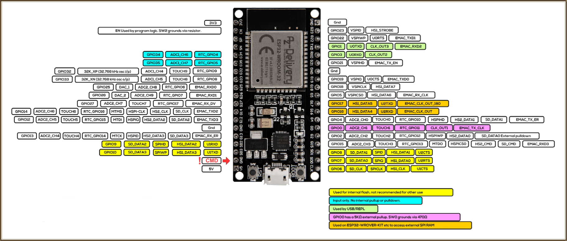
| AZ Delivery NodeMCU ESP32 | !  |
 |
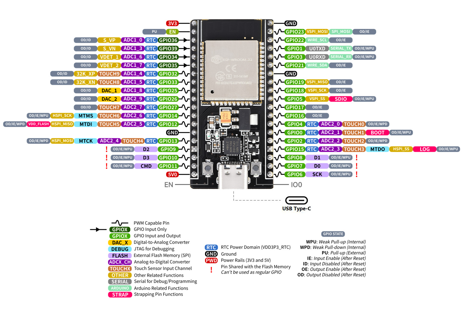
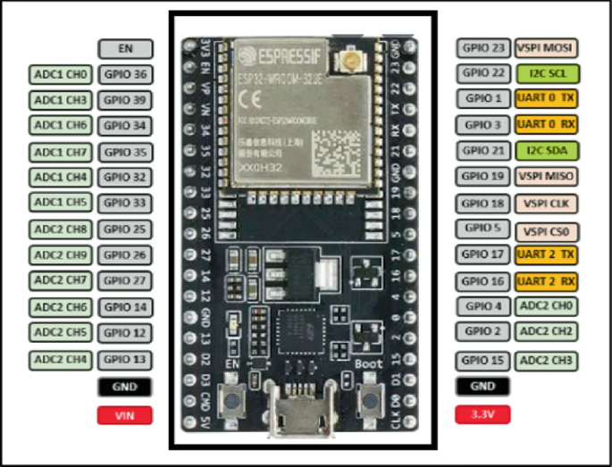
| ESP32 NodeMCU 32S | !  |
 |
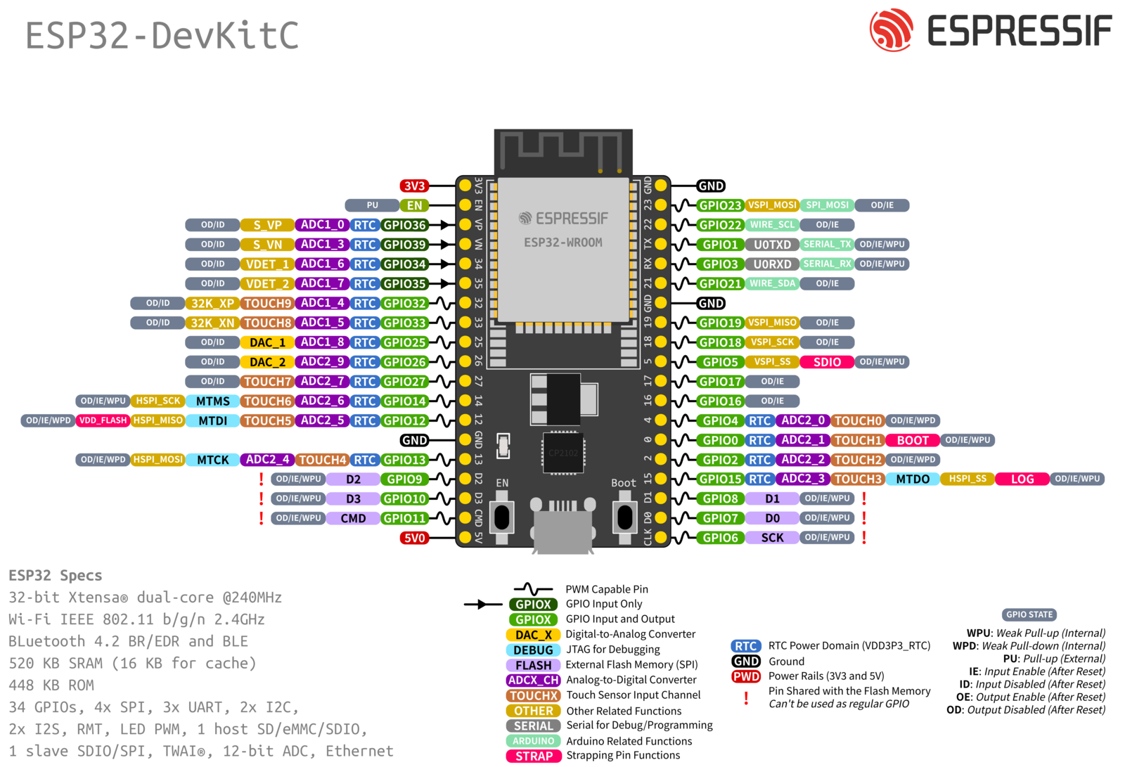
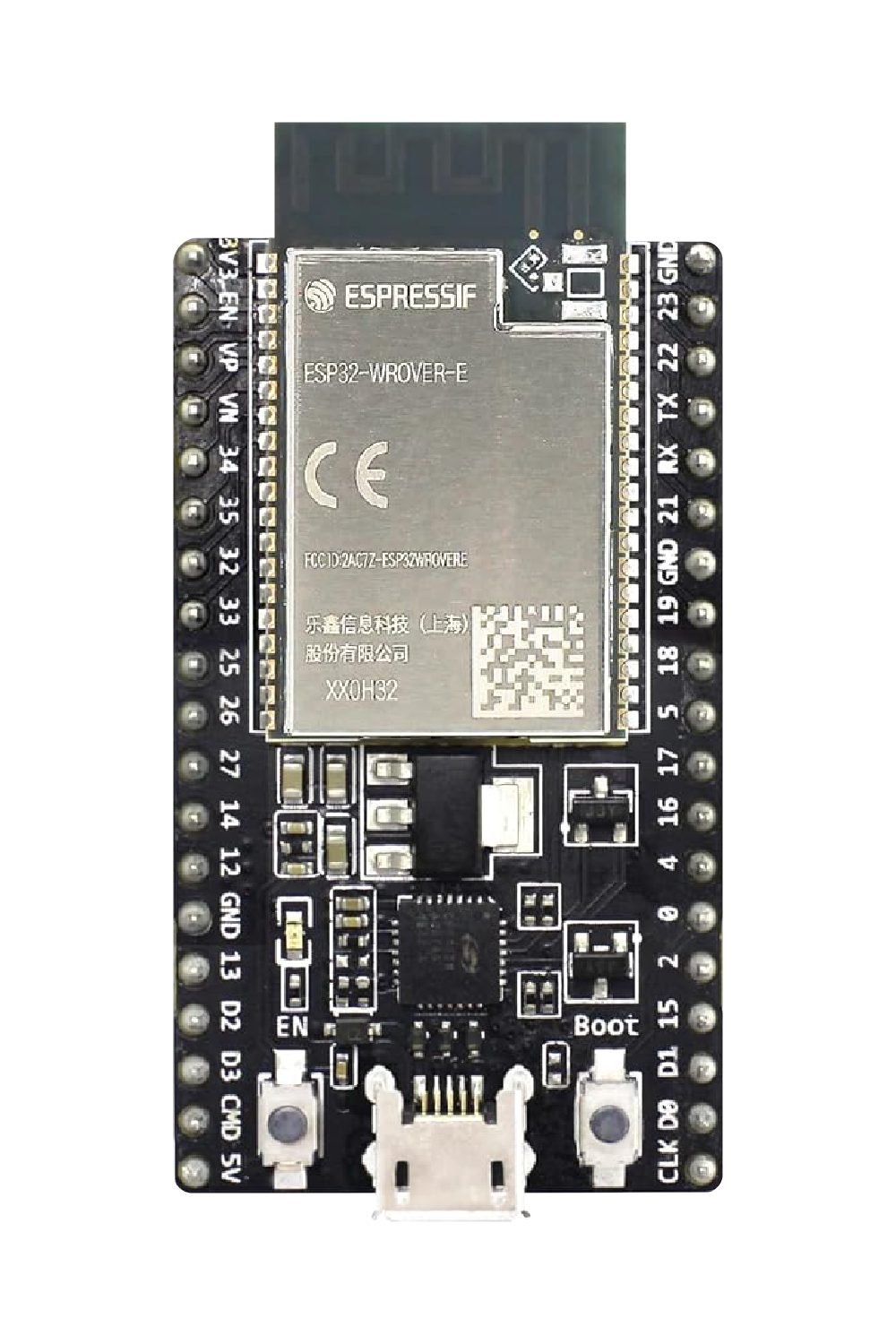
| ESP32 VROOM 32D (38 pins) | !  |
 |
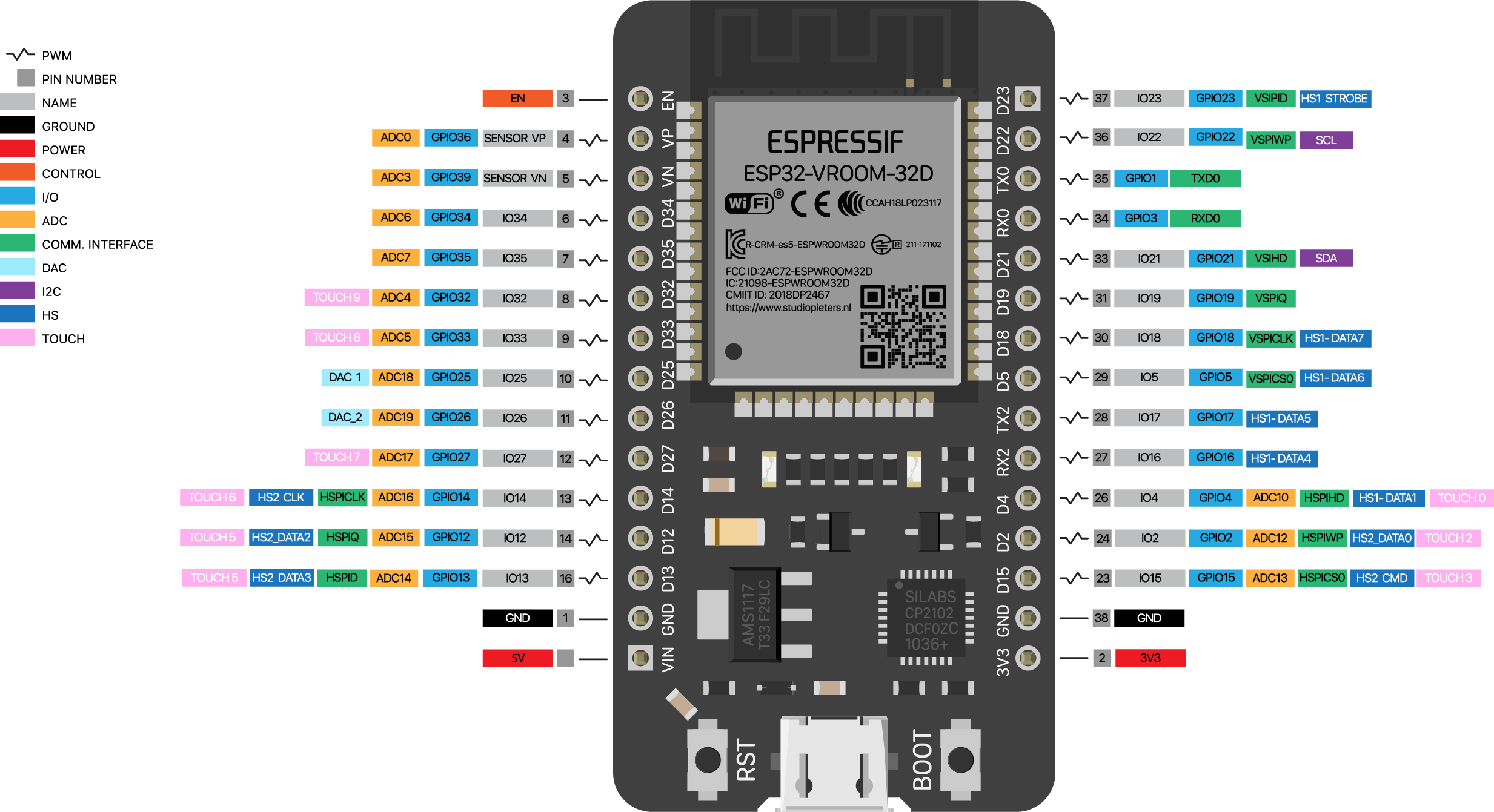
| ESP32 VROOM 32D (38 pins) | ! |
|
| ESP32 VROOM 32D (30 pins) | !  |
 |
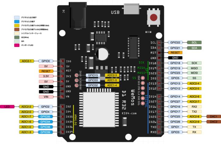
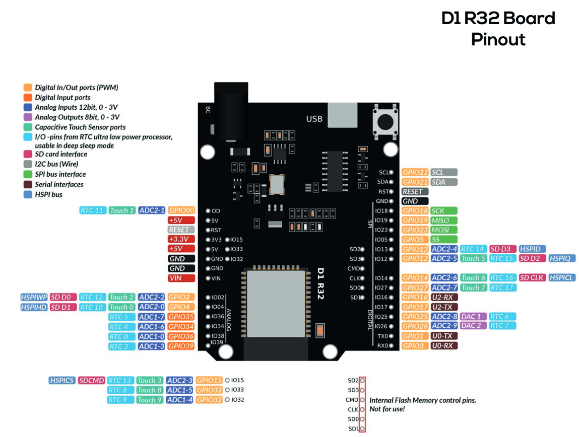
| ESP32 D1 R32 | !  |
 |
| ESP32-CAM | !  |
 |
| ESP32-C3 Super Mini | !  |
 |
| ESP32 C3 Wroom-02 | !  |
 |
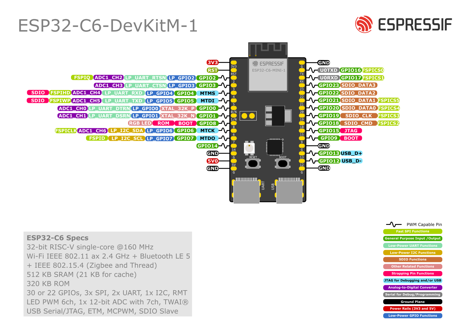
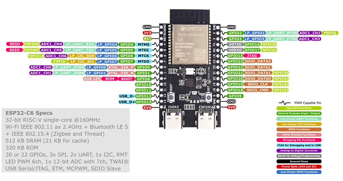
| ESP32-C6 DevKitM | !  |
 |
| ESP32 Wroom-32UE | !  |
 |
| ESP32 EVB | !  |
 |
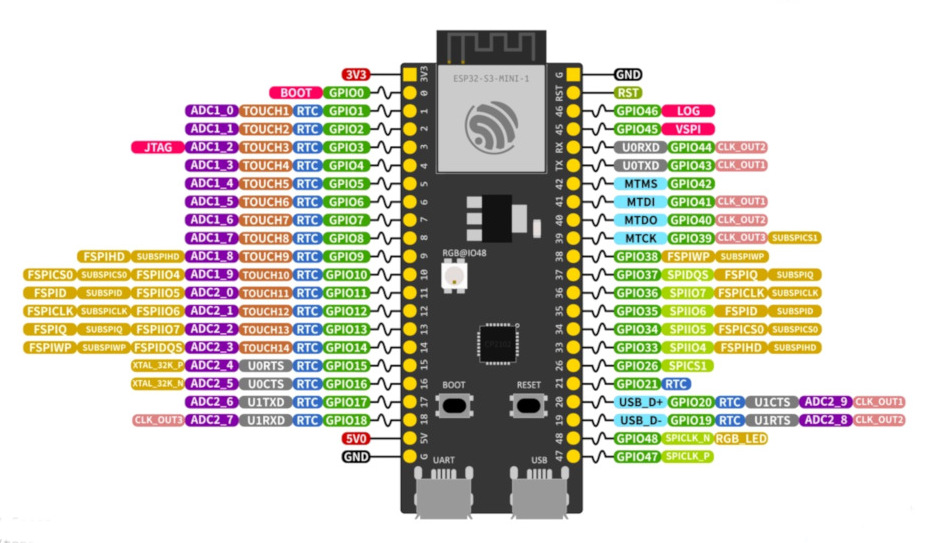
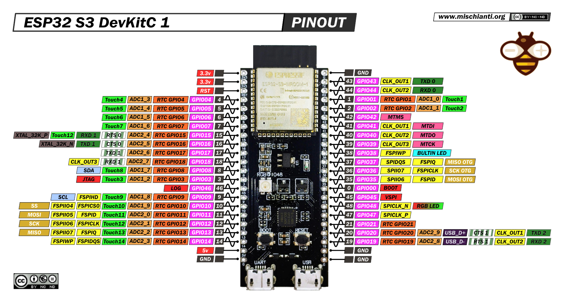
| ESP32-S3-DevKitM-1-N8 | !  |
 |
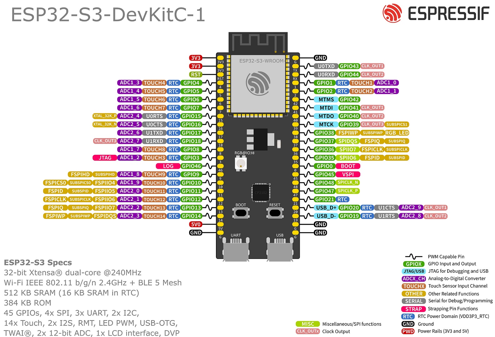
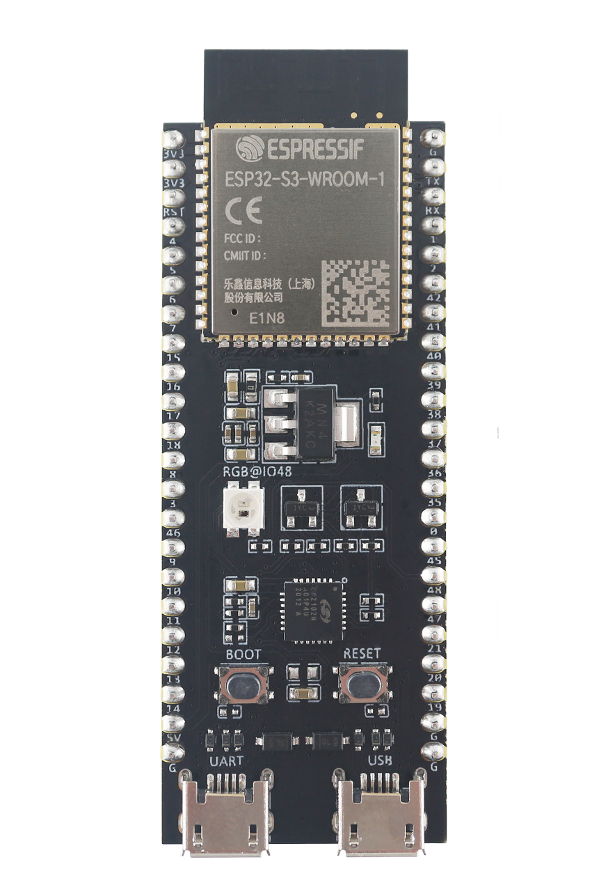
| ESP32 S3 Wroom-1 | !  |
 |
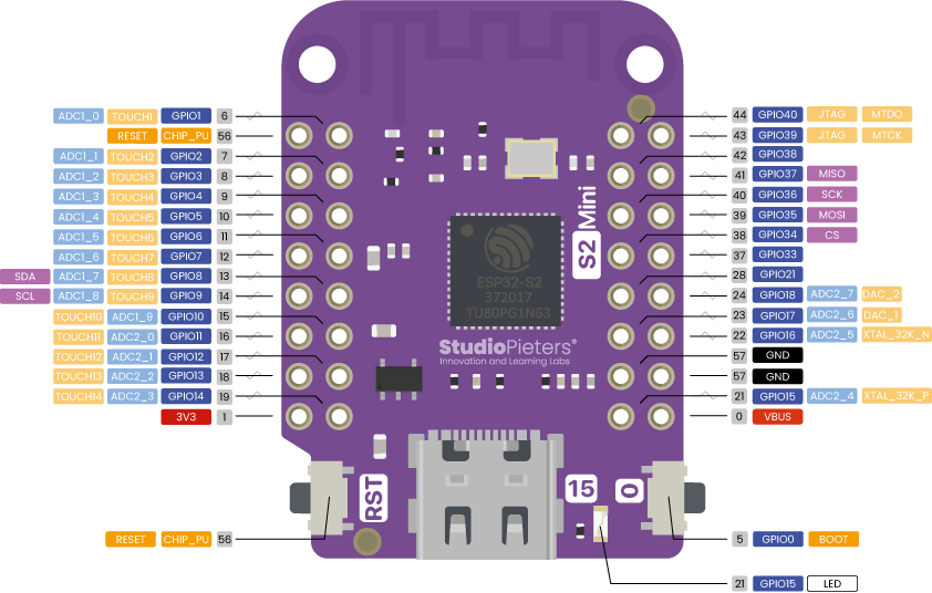
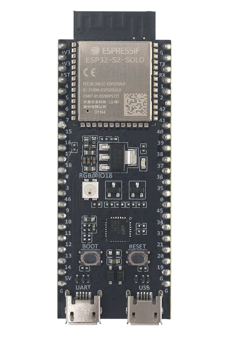
| Esp32 S2 Mini V1.0.0 | !  |
 |
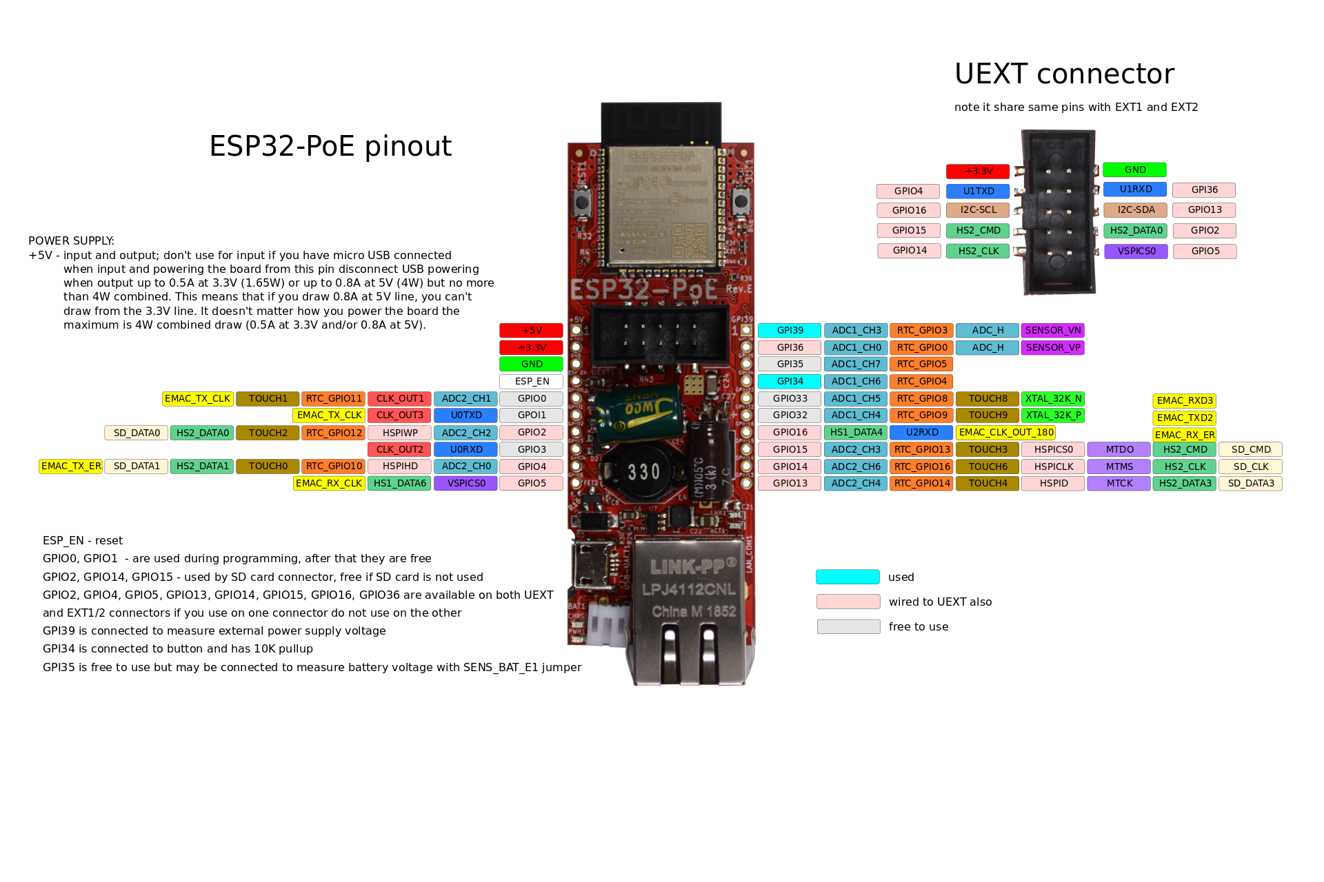
| ESP32 POE | !  |
 |
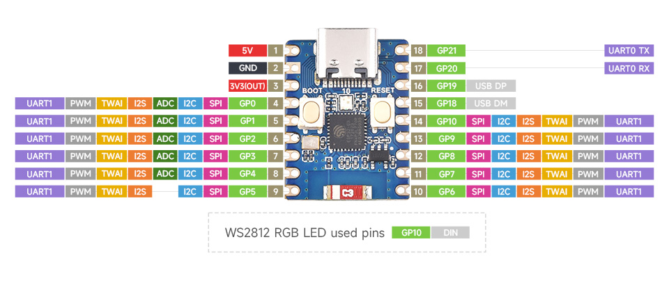
| ESP32 C3 Mini | !  |
 |
| ESP32 C3 Zero | !  |
 |
| ESP32 C6 Zero | !  |
 |
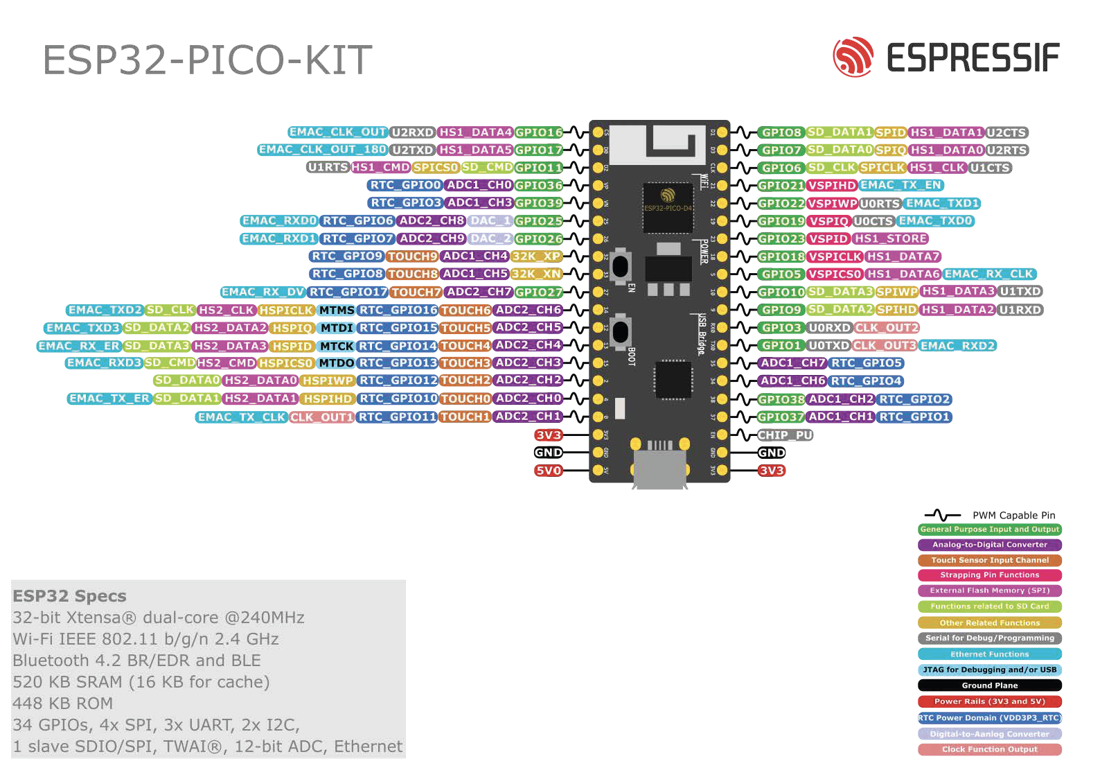
| ESP32 Pico Kit v4.1 | !  |
 |
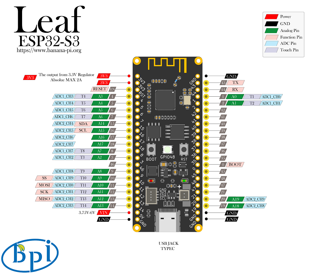
| Leaf S3 | !  |
 |
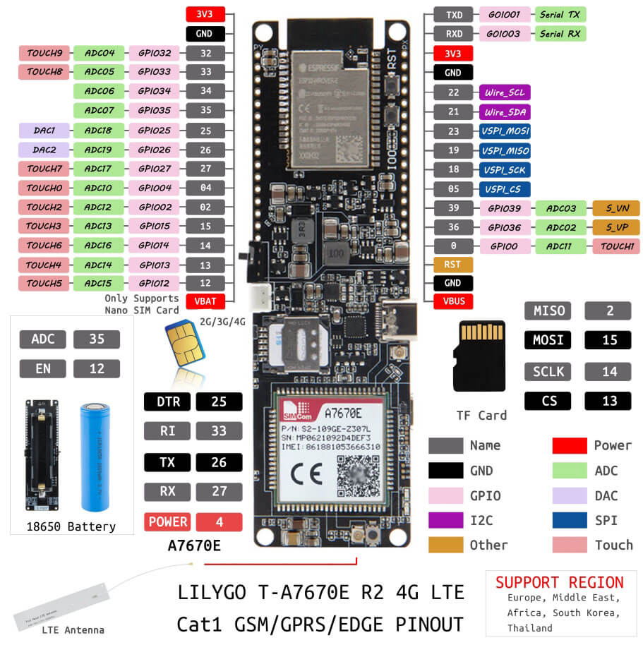
| Lilygo T-SIM A7670x | !  |
 |
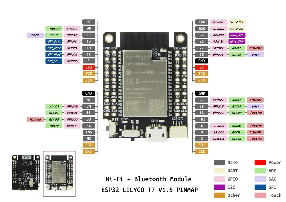
| Lilygo T7 Mini32 v1.5 | !  |
 |
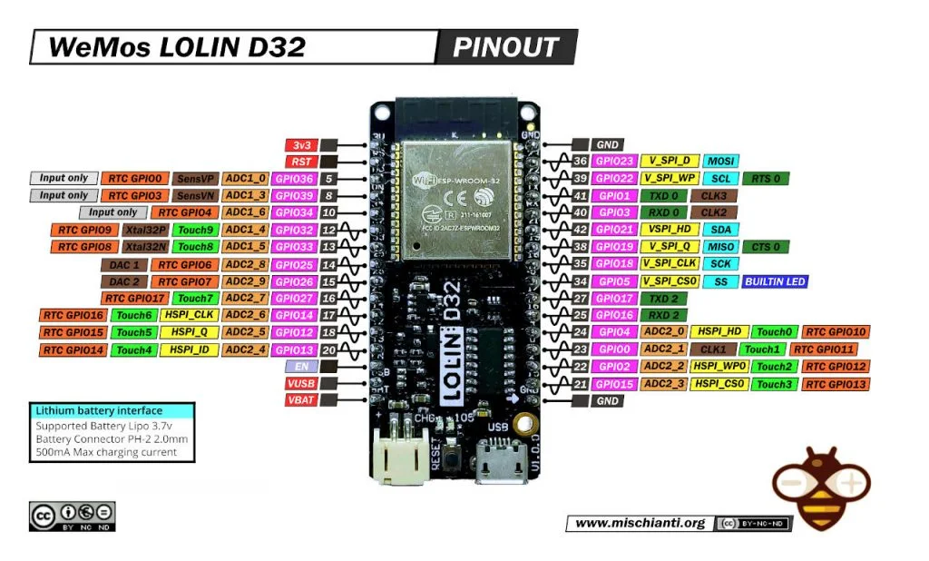
| Lolin D32 | !  |
 |
| Freenove ESP32-S3 | !  |
 |
| Freenove ESP32-Wroom | !  |
|
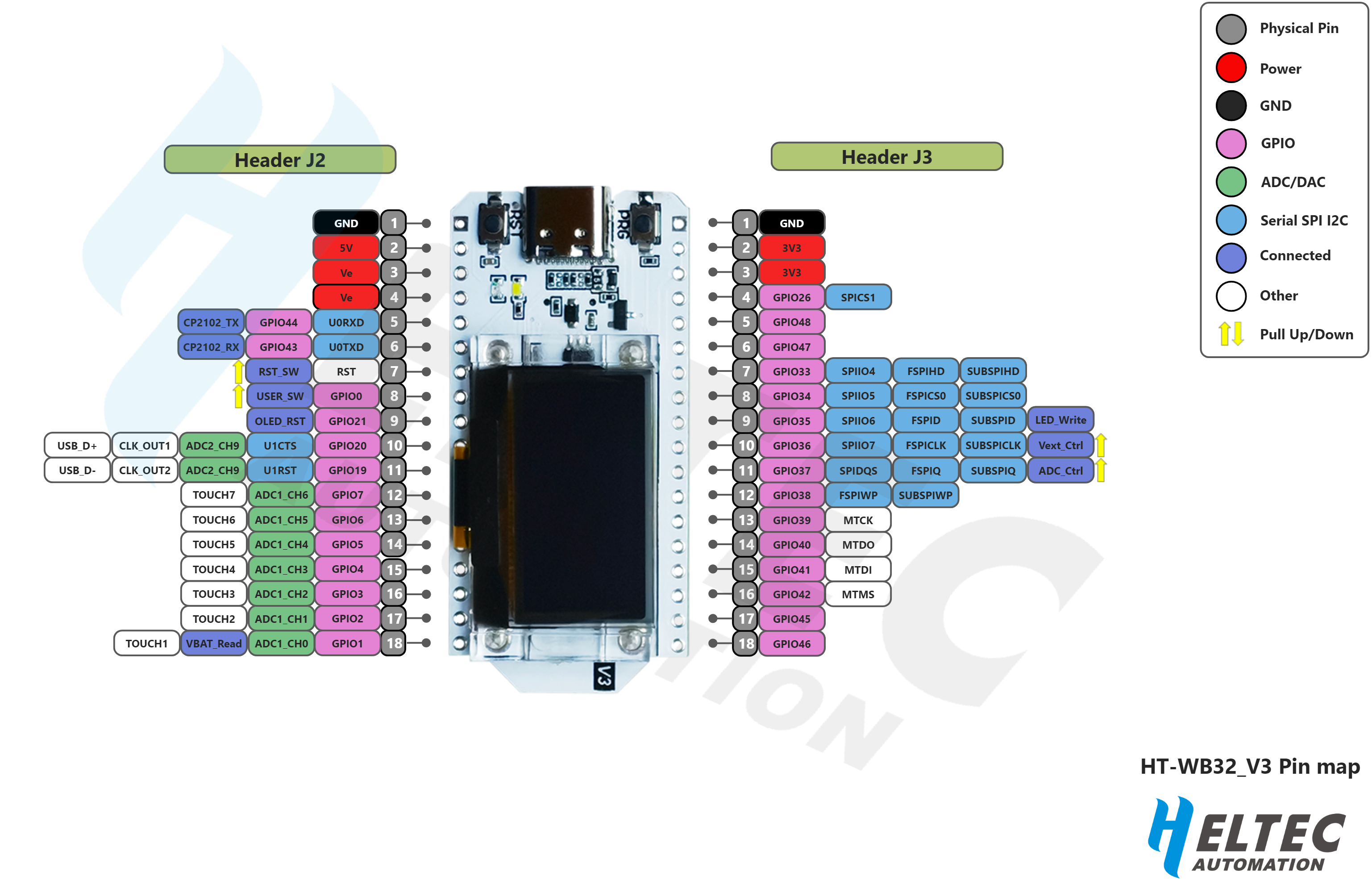
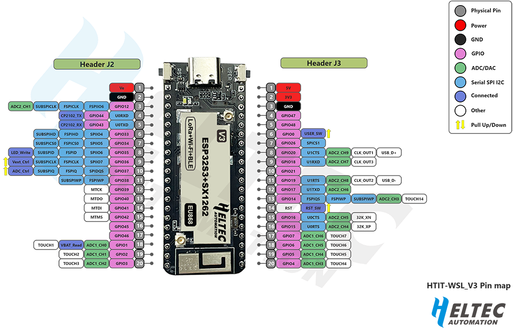
| Heltec HT-WB32_V3 | !  |
 |
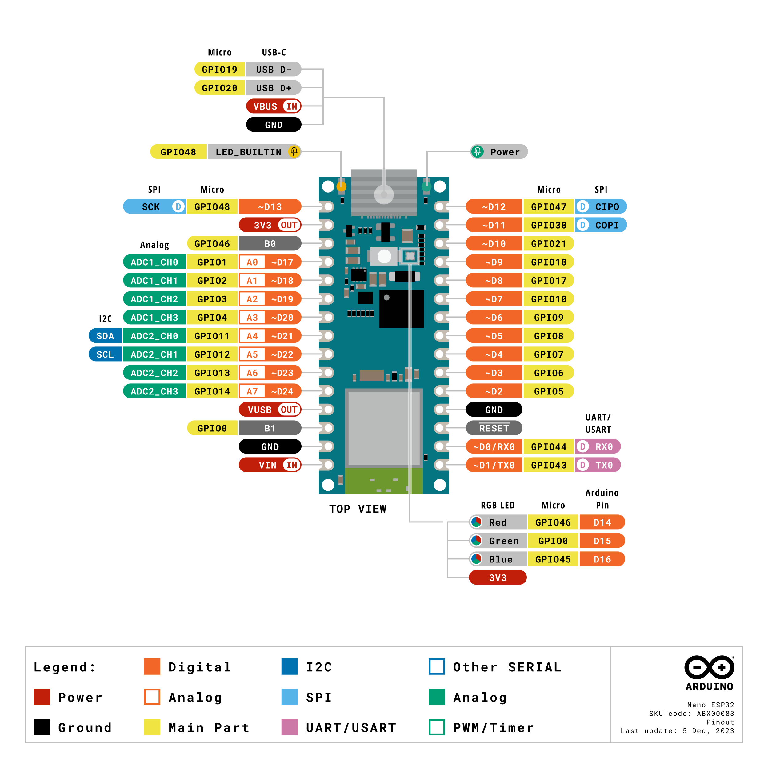
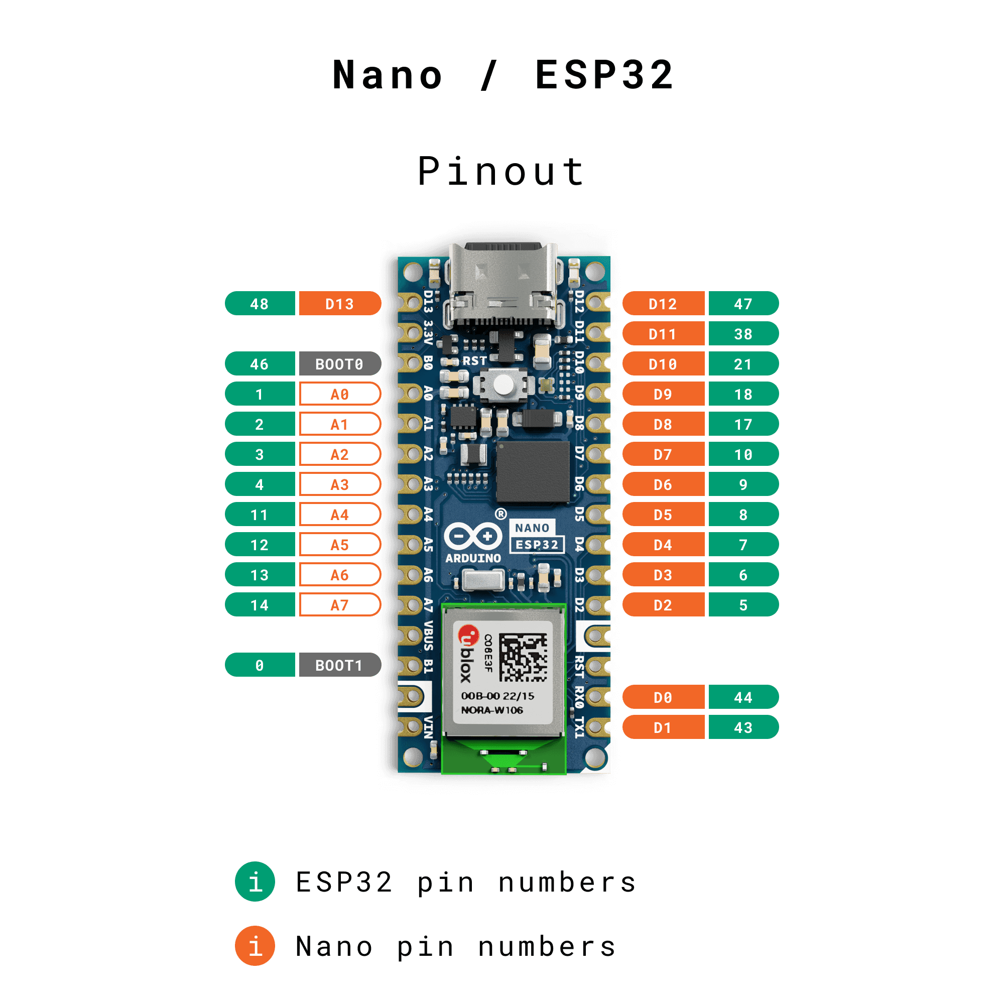
| Nano ESP32 | !  |
 |
| Nano ESP32-C6 | !  |
 |
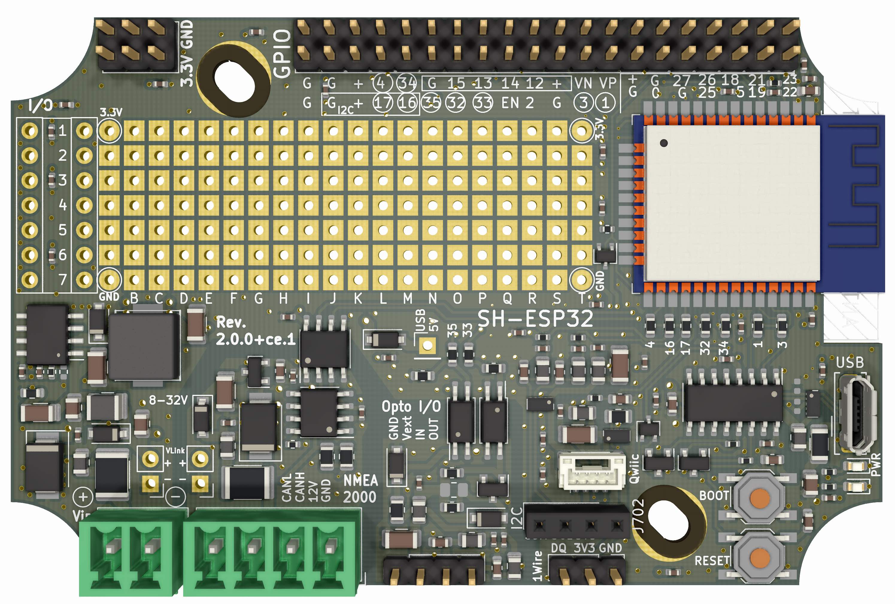
| Sailor Hat ESP32 | !  |
 |
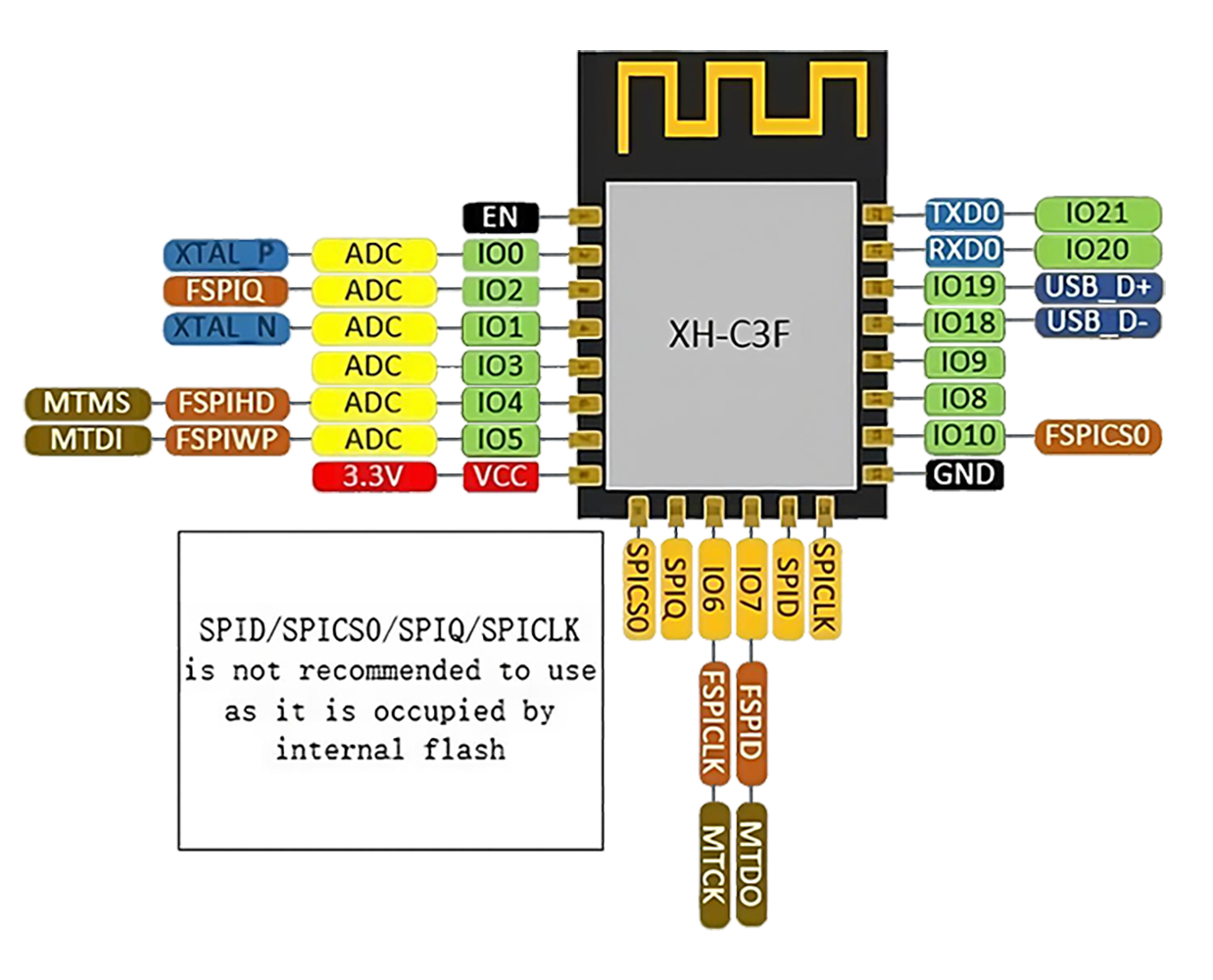
| SparkleIoT ESP32-C3F | !  |
 |
| StickLite-V3-ESP32S3 | !  |
 |
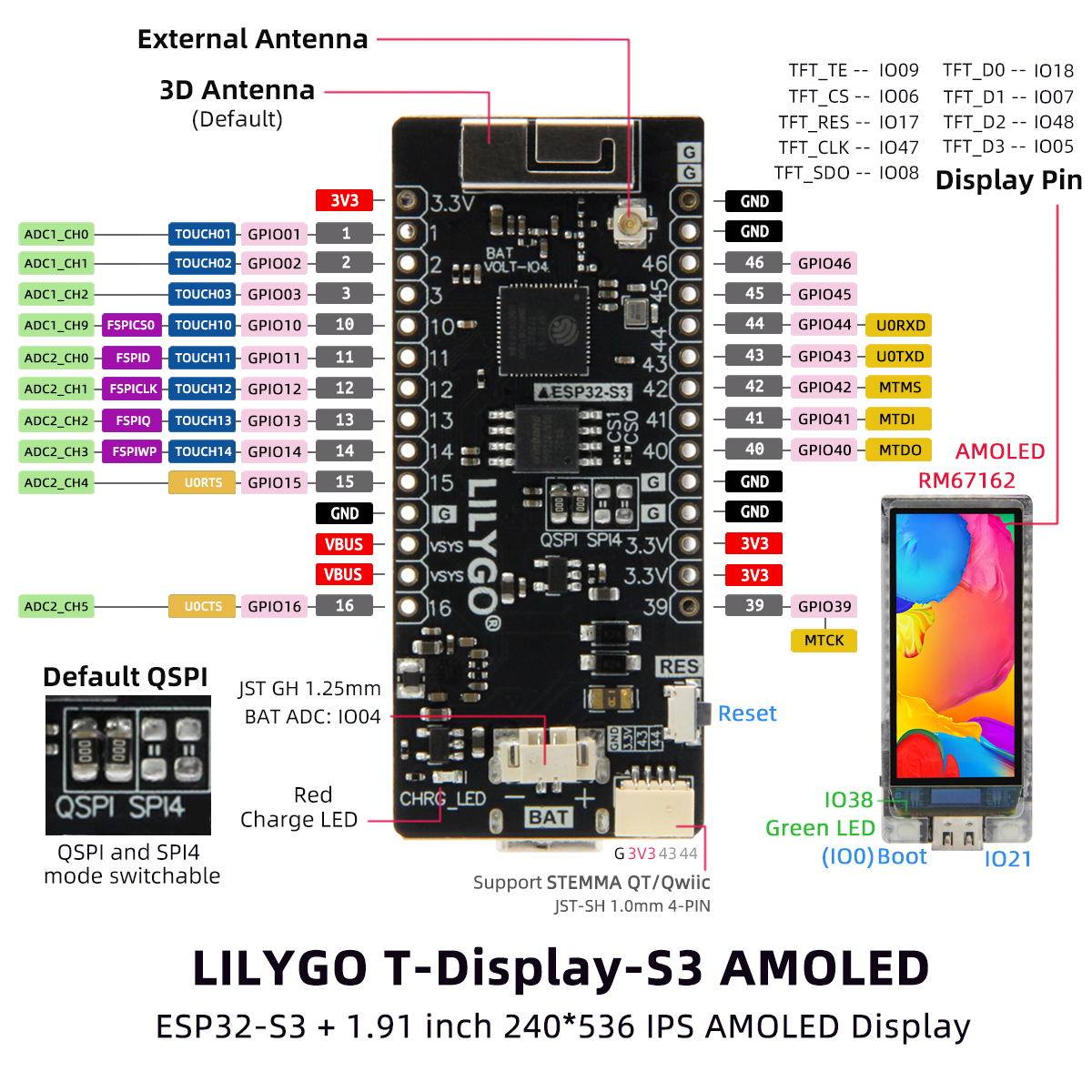
| T-Display S3 AMOLED | !  |
 |
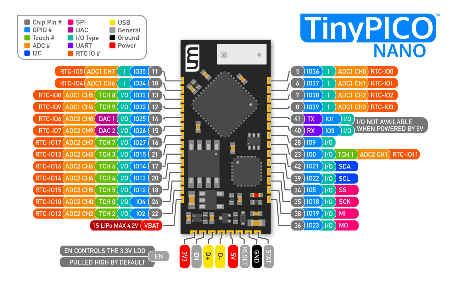
| TinyPICO Nano | !  |
 |
| TinyPico V3 | !  |
 |
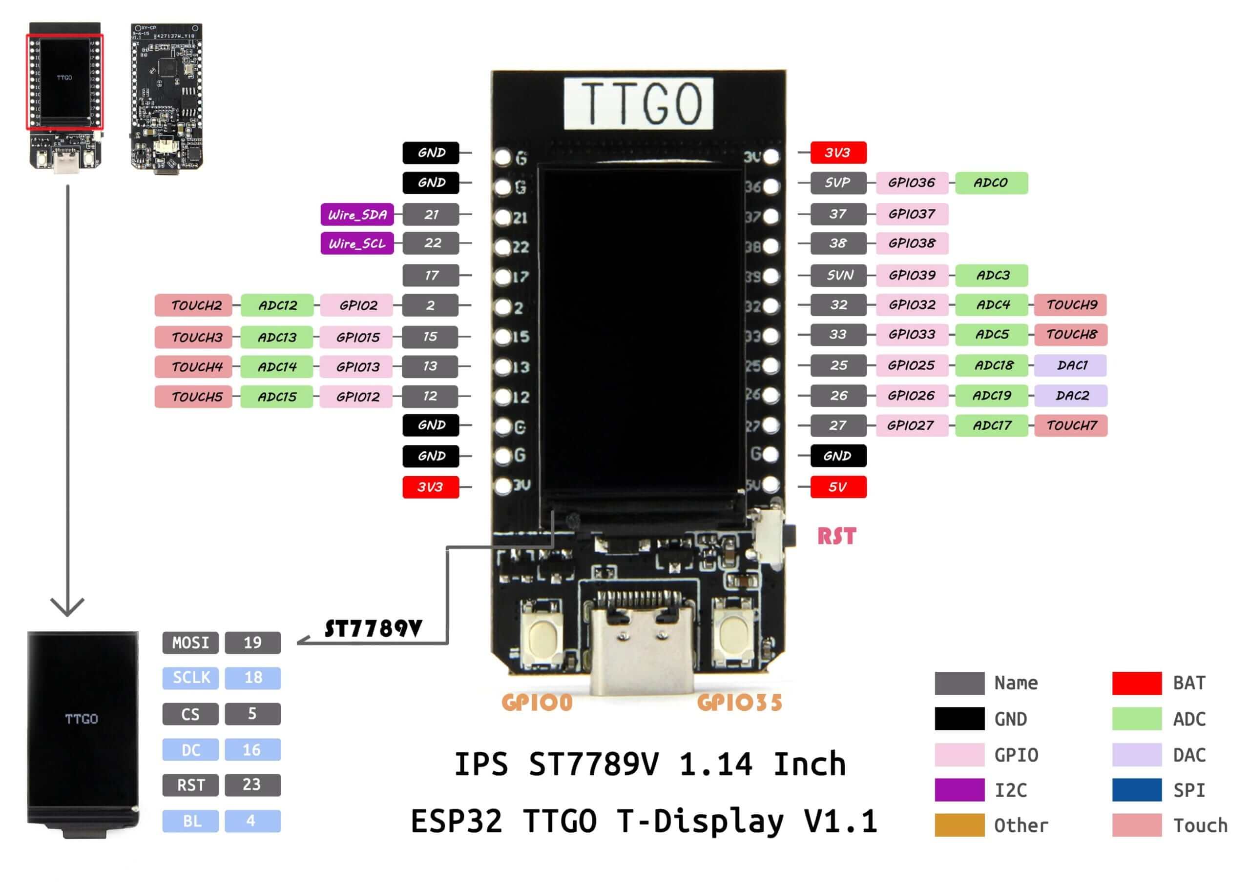
| TTGO Display V1.1 | !  |
 |
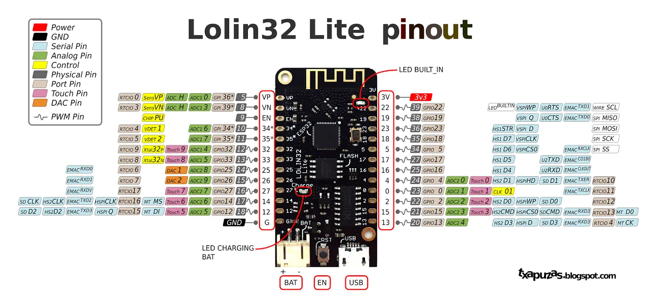
| Wemos Lolin32 Lite V1 | !  |
 |
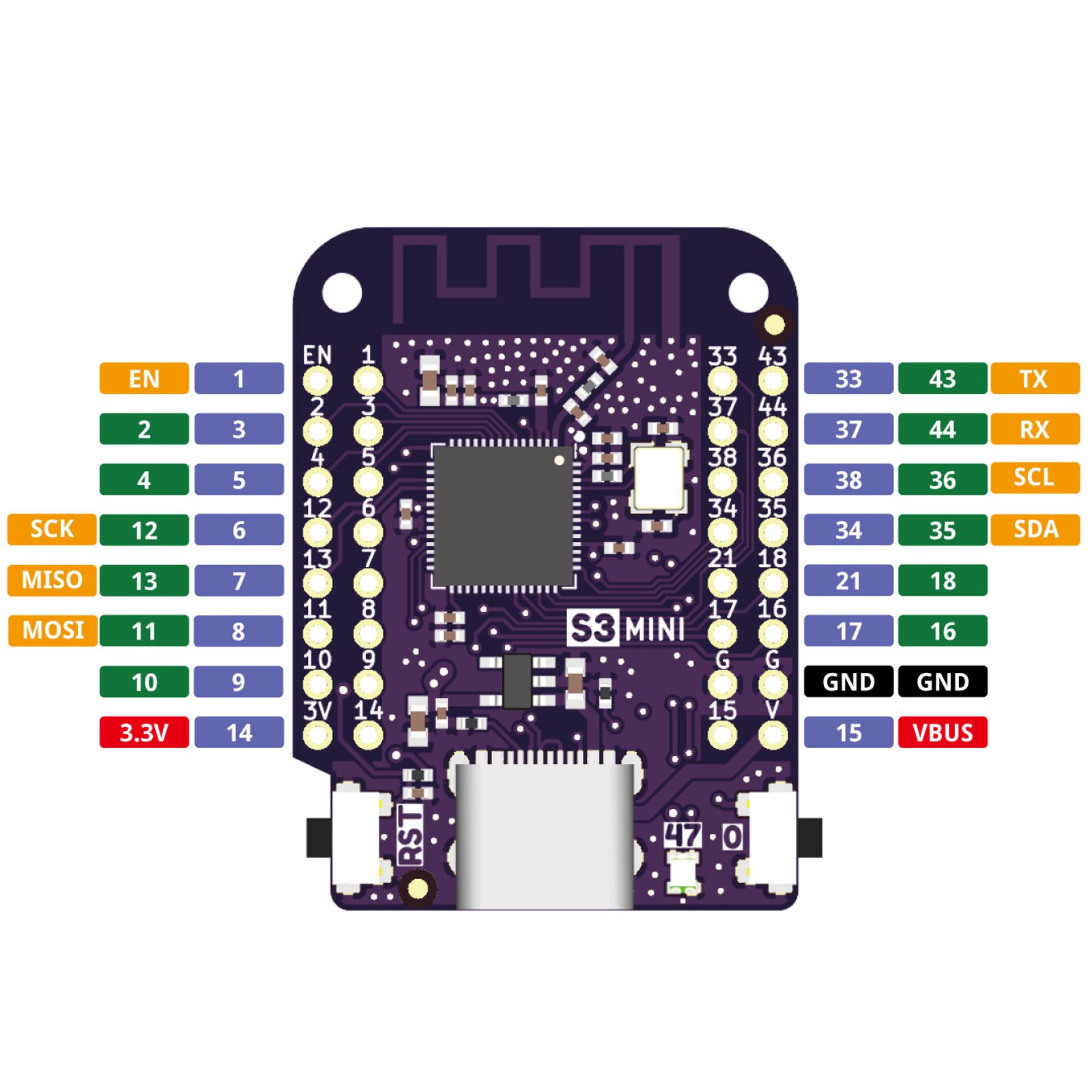
| Wemos Lolin S3 Mini | !  |
 |
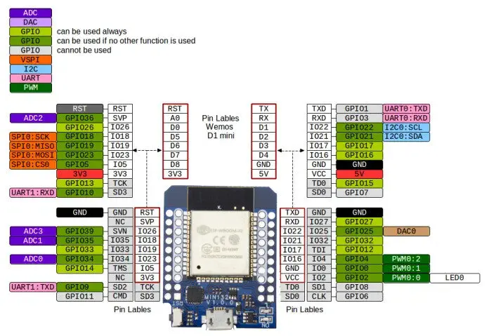
| Wemos D1 Mini ESP32 | !  |
 |
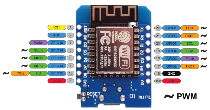
| Wemos D1 Mini ESP8266 | !  |
 |
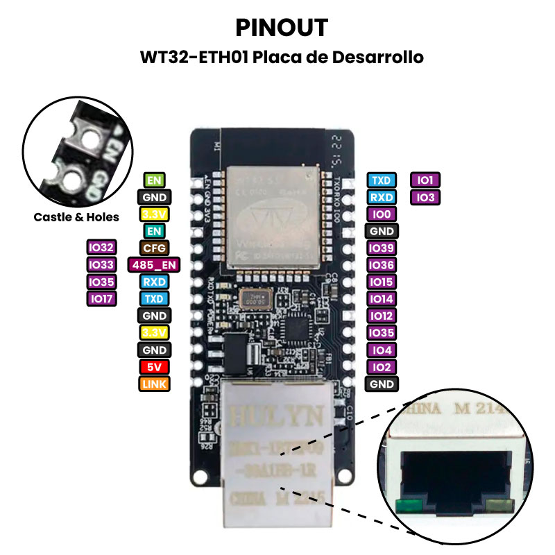
| WT32-S1-ETH01 | !  |
 |
| NodeMcu ESP8266 | !  |
 |
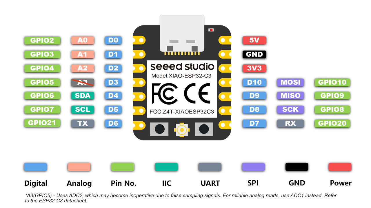
| XIAO ESP32 C3 | !  |
 |
| XIAO ESP32 S3 | !  |
 |


