opulo-inc / lumenpnp Goto Github PK
View Code? Open in Web Editor NEWThe LumenPnP is an open source pick and place machine.
License: GNU General Public License v3.0
The LumenPnP is an open source pick and place machine.
License: GNU General Public License v3.0


What values have these parts (from the mobo board):
R1, R2, R15, R16, R17, R33, R34, R35 |-in BOM says only->| R_Small
Add lower roller bearing adjusters to left Y axis gantry and also cable chain nut cutouts and bolt thru holes.
lefty axis gantry.zip
Hi, you asked in your recent YouTube video for some feedback on your pcb design.
It is impossible to build a "one fits all" pcb. You need a GPIO header to make it easy to add all kinds of boards and stuff. If you run out of GPIO pins on the Mega just use pins of things most people likely will not need anyway. Also add GND and V to this header. This way anybody can design another board/sensor/anything and connect it using just one header. If some mod or board gets really popular you can add it in a later revision.
Oh, and I do not recommend using some sort of 12v heat gun. They need a lot of power so your power supply have to be able to provide a lot more power (like 600w or even more) and you need pretty beefy, not very flexible cables to supply this amount of power (600w@12v = 50amp -> AWG8 wires) not to mention the cost of a good 800w 12v psu. I think you best option is to either just use an oven or to use the handpiece of an 858D hot air station. You can buy them for ~$12 and they even include a temp sensor. Not every paste needs the same temperature and I think it is not a great idea to use something without temperature control. This adds a lot of complexity, but I think it will be worth it as you need good solder joints to get something usable.
All CAD for the Index frame is currently done in Fusion 360. All CAD should be switched over to FreeCAD so that:
We currently use two opamps and an instrumentation amplifier to process the signal from the vacuum sensor. This signal is then sent to an ADC pin on the STM32F4. These parts are expensive, and it is difficult and less than ideal to implement reading from an ADC in Marlin.
The HX711 is an ASIC designed for processing signals from load cell Wheatstone Bridges (which is effectively what our vacuum sensor is). The HX711 also provides a digital interface for this data, so no ADC usage is necessary.
It's unknown if this switch will work; some investigation with the chip and how difficult it is to implement into Marlin still needs to be investigated.
Added holes and slots to install the common ramps endstop board (mechanical endstop switch) on front left leg (Y zero switch). Based on @sphawes front left leg v 1.1.0

I know this board is a little more expensive than using simple endswitches, but is very common, so I think quite a few people might use it
It also has some cool leds on it, and usually comes with cables already).
I've also added some slots for PTH terminals to fit, so no need to cut them at all.
Able to use wooden screws to hold the PCB, but standard M3 thread also does the work
Had to print with supports to hold the hanging slots.
I've printed the 1st version at 100% and had to do some hammering to fit the 20x20 extrusions in place. This time I've printed with 101% size to compensate for material (PLA) shrinkage (thanks arturo for the tip). Extrusions now still fit firmly yet, with no difficulty.
I've though of adding some supports directly to the CAD file to support the recess, but I was worried about that big bridge on the original foot gap, and was going to print with supports anyway.
See some attached pictures. The total size of the recess was bigger than the board because I was thinking about some extra space for the connector to attach/detach, but in the end, the recess was so shallow that it was not necessary (maybe completely remove the PCB recess, leaving only holes and slots)
I ended on removing @sphawes original endswitch holes, but maybe a mixed solution with both options might add some flexibility on final solution.
STEP FILE attached into a zip file
IndexPnP_1.1.0b_front-left-leg_ramps_endswitch v5.zip


I like the lens ring.
These is one small thing that could be done to increase contrast and reduce lens flares.
Instead of having 8 LEDs would it be possible to have 9? This way, each LED's possible internal lens reflections will be between the opposite two, not right on top of one. This will be true for every LED, and will make the lighting a lot more even.
I was thinking about changing the Nema11 with hollow shaft to a different angular positioning system.
It seems to be very difficult to find such a motor here in Brazil, so I'm planning on using the same standard NEMA17 used on other axes.
I will try the approach on this drawings (really sorry for the ultra low quality on hand drawing, absolutely nothing is on scale).
Any thoughts to improve this idea??

The Gergber files for piggyback in REV000 folder are affected by problems which are described in Controlling 30 PnP Feeders! video
Should not be used for fabrication any more.
If I'm not wrong the board at piggyback.kicad_pcb is already updated with fixes.
have you thought of using a FTDI chip for the usb to serial for the ATMega..
in my experience the CH340G has caused issues in some of my designs (automotive diagnostic tools) usually just poor performance and compatibility issues with MacOS, these could just be my implementation but ive found the FT230x chip is more reliable, plus at least in the land down under is cheaper than the CH340G $7 vs $3
The frame BOM is out of date, and needs to be updated with good sources for purchase.
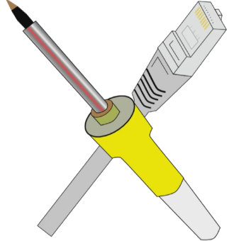
The feeders need some way of knowing what slot they're in. The current method uses a voltage divider on the feeder floor, but the chance of voltage drop across the connector makes this less than ideal for reliability.
There are quite a few ways to do this, but a quite good proposed solution is using one ID resistor on the feeder floor PCB, and using that in conjunction with a resistor on the feeder building a voltage divider. Wiring it this way will help remove voltage drop across the connector as a factor. A wiring diagram is below, assuming an RJ45 connector:

This needs to be tested to ensure it works reliably. Resistor values and subsequent ADC readings also need to be calculated for 32 discrete IDs. If this does not work reliably, another method should be identified.
We intended to use an ADC on the STM32F4 to read an analog signal from the vacuum sensors. This is not a feature that is currently supported by Marlin.
Missing 4 m2.5 x 10 screws in the BOM
When the X gantry moves over a feeder so that the down camera can see the part ready to be picked, the Z gantries protrude far enough that they can interfere with the feeder's film tension arm.
The film tension assembly needs to be edited so that it does not stick up so far from the top of the feeder, or (preferably) so that it sits much farther back, and the Z gantries have no chance of interfering.
Hi guys!
Great job with opening files for this project.
I've spotted missing STL's for :
And also names in BOM not always correlate to those in STL folder.
Cheers!
I'm doing diff checks on Marlin to see what was changed, but it'd be super useful to know how you're wiring things up. Could you make a wiring diagram for RAMPS?
The indexing wheel design currently supports an N20 motor shaft with a small hole, expecting a shaft collar to be glued on. The wheel design needs to have the center hole updated to accept the output shaft profile of the TT motor. This includes designing a way to properly fixture it onto the shaft.
I suggest, to add extra 2 mm on the frontal face of the front X gantry.
The M5x45 screw I've used to hold the rollers have a 5mm lenght head, and some of the head remains exxposed, and will interfere with the linear rail (see pictures).


The head top is 1.35 mm above the surface. Those extra 2 mm in the frontal face would completely cover the screw.

There is 3.8mm of exposed thread in the back nut (I'm using a simple nut). I know that the nylon lock nut will be a bit longer, but I think it isstill enough to spare for increasing to the front face depth.

This is a suggestion. If not accepted, maybe adding a warning on the BOM to use M5x45 screws with head length smaller than 3.6 mm length to avoid this issue.
Change design of the carriages to use eccentric nut.
ie. this Eccentric Spacers - Amazon
This will help in tightening the carriage rollers onto aluminium profiles.
This is also opportunity to change the design to use one less roller/carriage by changing square pattern to triangle. This shouldn't impact stability of carriage and help tightening BOM.
The IRF540N isn't a logic level MOSFET. To fully switch on, it requires about 10V at it's gate.
If driven by a 3.3V MCU output, it doesn't switch on reliably and may heat up significantly.
For reliable operation, a gate driver circuit with appropriate supply voltage is required.
Could you upload your machine file for Open PNP, and or provide some documentation for what settings you used?
Here are instructions on where to find your machine file:
https://github.com/openpnp/openpnp/wiki/FAQ#where-are-configuration-and-log-files-located
I added 2- 3MM nut slots and holes so 2 screws can be threaded up so the lower roller bearing bolts can be pushed up so they will become tight against the rail and not fall down.
right y axis gantry.zip
The current switches on the REV003 feeders that detect film tension and tape presence are limit switches with a lifetime rating of 100,000 cycles.
We should switch these out for a hall effect sensor on the board like the SS39ET, and include a small magnet on both prints that actuate the switches.
This change requires:
-feeder PCB update
-feeder BOM update
-feeder CAD update
-feeder firmware update
The REV02 motherboard design has a number of THT footprints that cannot be assembled using a pick and place. As many footprints as possible should be switched over to SMT. Some footprints (namely stepper driver headers, and most connectors) should be custom, hybrid footprints that allow for both types of parts to aid with hand-soldering, and also supporting being pick and placed.
The BOM for the Feeder and needs to be updated, including good sources for purchase.
After trying to get OpenPnP to accurately zero the Z axis, I think it might be necessary to add an extra endstop on the axis. I have designed a quick mount for one (attached below) and this has proven to work on my machine. (please bear in mind I am still using a RAMPS 1.4 board)


Here are the files: z-axis-endstop.zip
Cheers.
Cool project!
I see at least some of this repository has a license, but the root is missing a LICENSE file and the README does not mention anything about the license. Without a license the default is copyright.
Ploopy_feeder is CERN Open Hardware Licence v1.2. firmware_marlin is GPL-3.0. What should the rest be licensed under? I would suggest GPL-3.0.
Hi Stephen.
Can you include in this repository all KiCad documents in PDF.
It's better for view more fast. (And if don't working with KiCad) ;-)
Thank a lot.
We are using a few UART ports on the STM32F4 to communicate with feeders and other peripherals over RS-485 (thanks to the MAX3485 chip). Marlin does not currently have support for RS-485, or generally sending data out over a second serial line.
The front feeder rail is too far in the -Y axis (towards the user). Shifting it back 20mm will allow the nozzle and the camera to easily see the pick area. This will also likely allow a wider range of other feeder designs to work with pre-pick vision.
The cable chain files are from thingiverse files#11978 ,2951196. WARNING I DID NOT CHECK THE LICENSE FOR THESE PARTS. (so I don't know what it is Sorry). The end mount I created form the STL file. I am still working on the other end for the legs and also the mods for the front and back legs. (I plan on doing both options since my electronics is on the back and yours is on the front.
cable chain and ends.zip
Note: cable and chain file 11978 license cc-sa
print in place file 2951196 Creative Commons - Attribution - Share Alike license.
JLC have reject the indexing wheel.
Order Reviewed:2020-07-08 18:00:33
Check the audit failed reason:
the corner cutout is too small, kindly fix to hit our capacity 6x6mm at leat.
Unless I missed something, it needs to be printed 8 times, not 6.
4 pcs for Y carriages (2 pcs each)
2 pcs for the X carriage Front
2 pcs for the X carriage Back
There is no assembly instruction for the mechanical part of project.
I can help with that using Overlaf
The holes on the spoolHolder is too tight. Should be increased to around 3.2-3.3mm. Currently they are 3mm which requires your 3D printer to be extremely precise in it's printing.
I'm not an expert about KiCad but I assume files like
pnp/pcb/mobo/fp-info-cache
pnp/pcb/mobo/.sch-bak
pnp/pcb/mobo/.kicad_pcb-bak
should be added to .gitignore and removed from repository?
Please refer to articles:
Project and libary setup for sharing and collaboration
fp-info-cache purpose
Of course the same rules should apply to:
pnp/pcb/piggyback
feeder\pcb\feederFloor
feeder\pcb\indexingWheel
feeder\pcb\mobo
It is possible to communicate with the Index feeders through OpenPnP, but a tremendous amount more functionality is available if we create a custom feeder type for the Index in it.
During work the carriage can apply enough force to the rail to twist on it through the metal having very slight flex, but more from the lash in the bearings and touching surfaces.
This won't be as much of a problem near the end of the rails, where just the carriage lash exhibits, but towards the middle of the rail the effect will be enough to cause the head to shift position measurably. These uneven-by-position effects are the hardest to calibrate out in software.
The effect would worsen over time with wear, and also become more apparent if people build wider machines.
I suspect going to 20w x 40h rail for that one rail would reduce this effect by 75% or more and reduce wear on the rollers considerably. Remember, that rail is sitting on 2x 20x20 rails, one each end, so each of those rails is only carrying half the load, and the load is centered on those rails.
The feeder is currently only secured to the front rail using gravity, and a bit of friction from the pcb. A small latching mechanism needs to be added to the feeder that:
In REV02 of the motherboard, some power conditioning was added for the VDDA pin on the STM32F407. However, the rail on the opposite side of the conditioning is not connected to the VDDA pin, and the VDDA pin alone.
The version of FDM-0020-00_up-camera-mount in the 'freecad' is missing the cut-out for the USB header pins. I have corrected this in Fusion 360 (STEP attached), but FreeCAD continues to baffle me.
Can you make the fusion 360 archive file available in the CAD repository?
All parts in this project are getting unique part numbers. You can read a bit about how these are made here.
Every part needs a unique part number and a colloquial name, and listed in parts.csv so that part numbers are not repeated. This is a master list that even includes parts that have been deprecated. Also, version.json needs to be built out so that every part number that is included in a build is referenced in version.json.
All CAD for the Index feeder is currently done in Fusion 360. All CAD should be switched over to FreeCAD so that:
Is the $70ish difference in price the only reason for going from the well OpenPnP supported Smoothieboard 5X to the clunky and so-so RAMPS board?
I've seen that Smoothieboards seem to operate steppers much more smoothly with much more elegant acceleration curves.
Or is that just me?
During assembly M5x35 don't fit into xIdlerMount and xMotorMount, M5x10 are too short.
M5x20 works like a charm.
Hello
I don't see any specs about what motor is actually used for the feeders in the parts list nor in any description.
The motherboard is fairly exposed when mounted to the bottom of the panel. A snap-on cover would be a great optional print for folks to have if they want to protect their motherboard.
A declarative, efficient, and flexible JavaScript library for building user interfaces.
🖖 Vue.js is a progressive, incrementally-adoptable JavaScript framework for building UI on the web.
TypeScript is a superset of JavaScript that compiles to clean JavaScript output.
An Open Source Machine Learning Framework for Everyone
The Web framework for perfectionists with deadlines.
A PHP framework for web artisans
Bring data to life with SVG, Canvas and HTML. 📊📈🎉
JavaScript (JS) is a lightweight interpreted programming language with first-class functions.
Some thing interesting about web. New door for the world.
A server is a program made to process requests and deliver data to clients.
Machine learning is a way of modeling and interpreting data that allows a piece of software to respond intelligently.
Some thing interesting about visualization, use data art
Some thing interesting about game, make everyone happy.
We are working to build community through open source technology. NB: members must have two-factor auth.
Open source projects and samples from Microsoft.
Google ❤️ Open Source for everyone.
Alibaba Open Source for everyone
Data-Driven Documents codes.
China tencent open source team.