Recently I got a pack of ESP breakout boards from CircuitSetup for building slightly more permanent versions of things. As others have remarked, it's not super obvious exactly how to wire things up. But if I really cared that much I'd just etch my own boards...
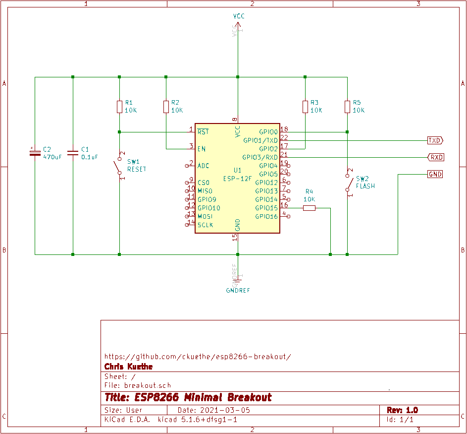
So here's the base circuit: all the necessary pull ups and pull-downs; the
common reset and flash buttons; some decoupling capacitors; and a UART header.
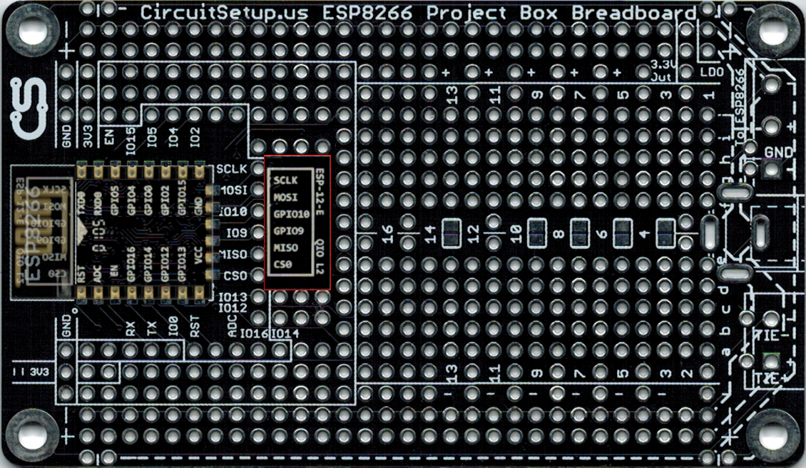
Let's take a closer look at the breakout board. Through the magic of photo
editing, we see how the pads on the ESP12 line up with the pads on the
breakout board. Yes, the UART pads on the ESP12 are closer to the top of the
image, and they surface closer to the bottom.
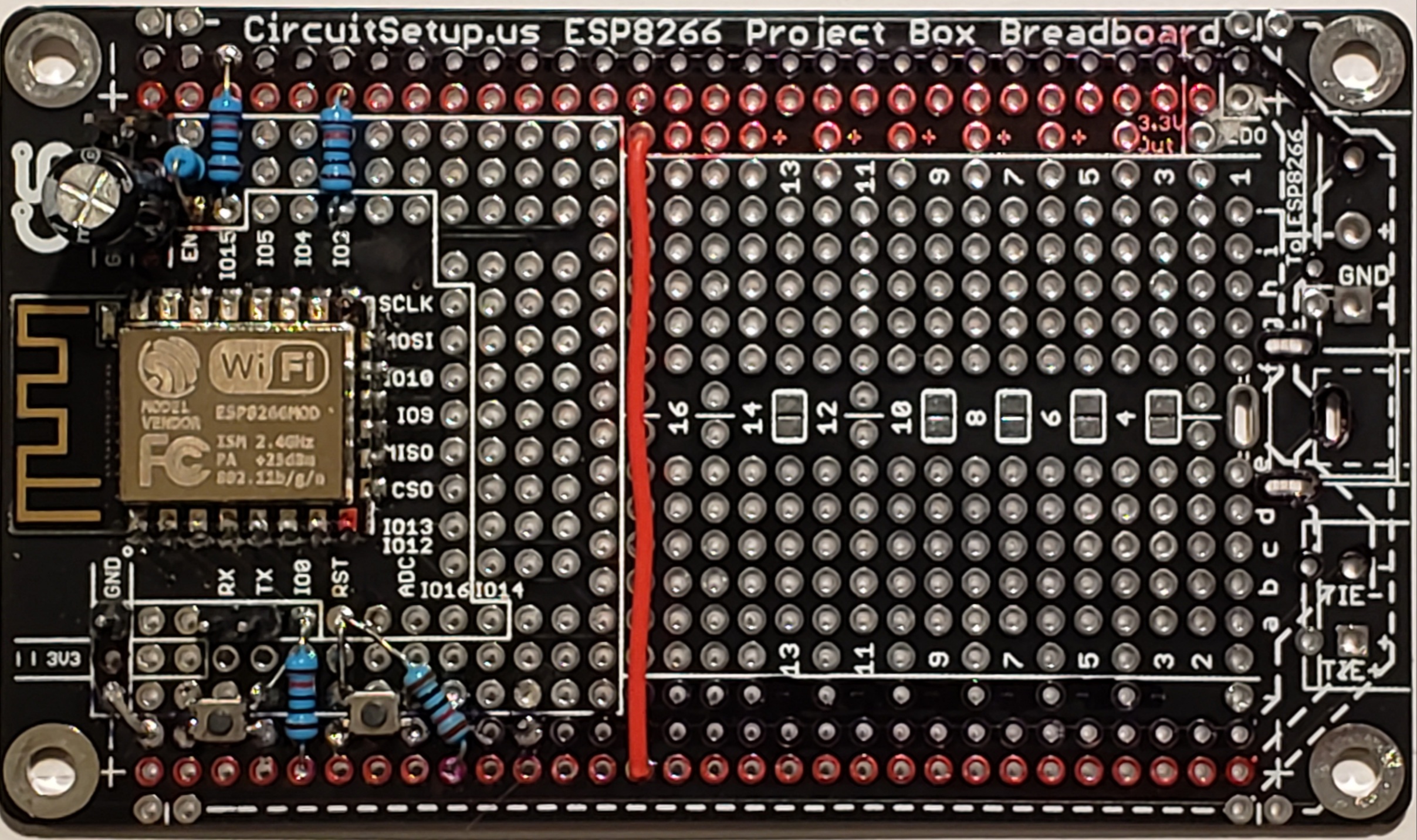
Finally, here's what that looks like when the basics are soldered in