Since we've built our own PCBs, the actual programming routine needs to take out each node and code it with the st-link via USB. This, in race condition, needs too much time to be applied. The idea is to leave the nodes attached to the car, and with the help of the LAWICEL CANUSB (can to usb interface) and Microboot (software updater) we can easily update them.
This is achievable with the help of a bootloader inside the memory of each node.
The bootloader is itself a program inside the memory of the microprocessor. Bootloaders usually provide a method of flashing new code to the device and initialize the hardware before running the main program.
This is possible due to the fact that the bootloader and the user program are isolated from themselves.

At every reset (hardware or software) the bootloader runs and check if a new code is available.

Datasheet: stm32f303k8
For this purpose, since we will use the Nucleo-stm32f303k8, we will see how is possible to use a bootloader for this Microprocessor.
The first thing to know is that all the nucleo by the ST have their own bootloader by factory (Not only the nucleo, but also the single mcu made by ST). The chip it's the ARM Cortex-M4, nevertheless buying it from ST company, it will have some default setting.
For us is impossible to modify this bootloader, the idea is to put a "layer program" in the flash memory before the user program.

From the image above we can see that the factory bootloader is for sure in the early memory pages from 0x0000 0000 to 0x0001 0000, and we can not access this location.
We will use the 64KBytes of the higher Flash Memory (from 0x0800 0000 to 0x0801 0000).
In the Boot program, opening the linker script (Demo\Boot\STM32F303K8TX.ld) we will set the start from 0x0800 0000 and LENGTH = 8K.
Meanwhile in the Prog program, opening the linker script (Demo\Prog\STM32F303K8TX.ld) we will set the start 8KBytes later, so it starts from 0x0800 2000 and LENGTH = 64K - 8K.
This is an open source Bootloader, compatible with some microprocessor families.
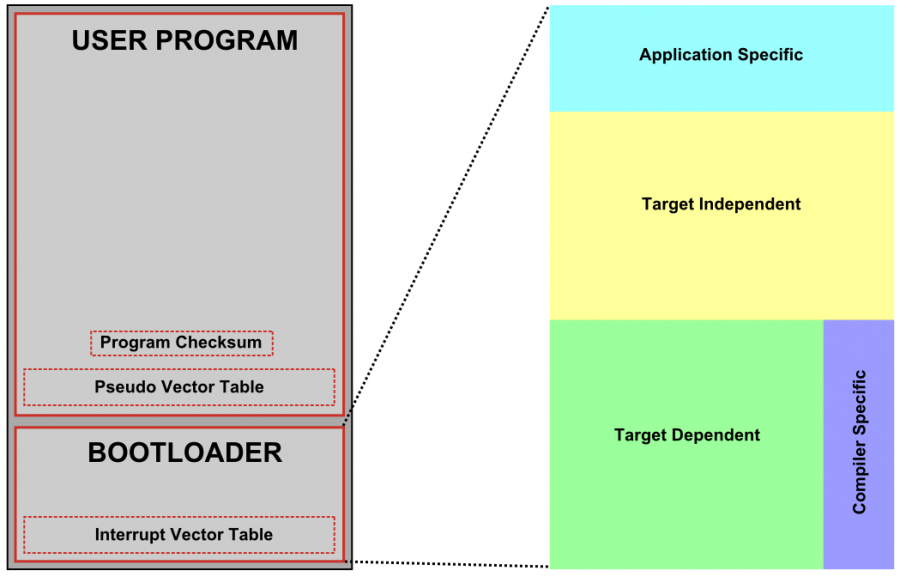
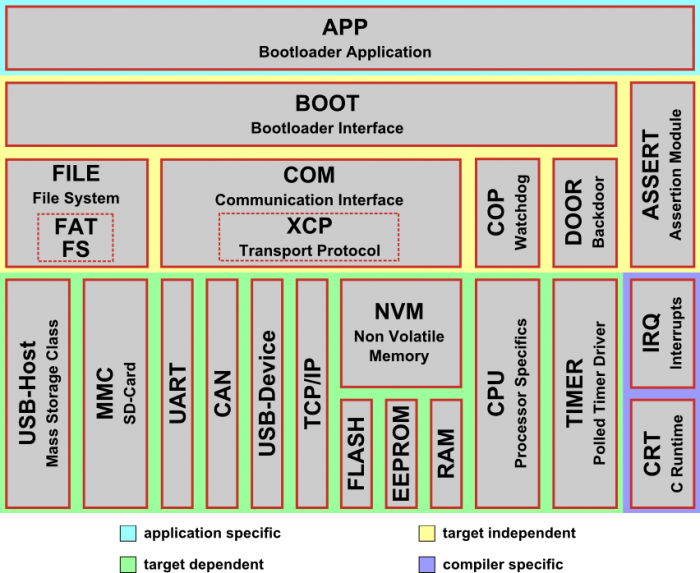
This is the general structure of OpenBLT.
The Application Specific have the function to modify the bootloader based on project specific needs. Here we can find the main() function, bootloader configuration file and hook functions. (Here we can enable the backdoor or handling watchdogs timers).
The Target Independent is the core of the bootloader, for our purpose. It handles the data transfer from the firmware file to the microcontroller's memory. We don't have the need to modify this part. This works with XCP protocol by ASAM, here can be found more information.
The Target Dependent is the only part that need some changes when porting the bootloader to a new microcontroller. It contains the low-level drivers for accessing the communication, timer and memory peripherals. Then there is a sub-part of the target dependent which is the Compiler Specific; It contains code such as the c-startup routine and the interrupt vector table, which typically needs a little compiler magic to link to the correct memory location.
The Controller Area Network is the protocol of a specific bus used mainly in the automotive field.
In our car, almost every node it's connected to the can-bus to have an easy and fast way to exchange information through the whole vehicle. It's based on a twisted pair of copper wire, with two 120 Ohm Resistor at both ends.
Each node have three fundamental parts.
- CPU or Microprocessor
- Can controller (often an integral part of microprocessor)
- Can Transceiver

N.B. Each node can transmit and receive, but NOT SIMULTANEUOSLY
The CAN-Bus use two differential signals, CANH and CANL, rispectively High and Low state. Creating a "Dominant" bit when CANH>CANL and "Recessive" one in the other cases. Having a Wired-AND convenction this will give the priority to the nodes with lower ID. The can is based on a CSMA/CD+AMP. CSMA stands for Carrier Sense Multiple Access, so each node have to wait for a prescribed amount of time of inactivity, before attempting to send a message. CD stands for Collision Detection, basically a letteral meaning and Arbitration on Message Priority (Lower ID nodes have the priority).
Doing an complete explanation of the can-bus is not the purpose of this project, but knowing what it is will explain why we are going to use it as the bus for updating our nodes
This are PCBs that we have made by ourselves.
MCU: STM32F3030K8
Transceiver CAN: MCP2551
External Clock: 12MHz Quartz
We can also use them for this project. The main difference between our wheel node and the nucleo is that Wheel Nodes doesn't have the programming mcu (stm32f103c8t6) so they need an ST-Link to write code in them meanwhile the nucleo have it on board so they are ready to be programmed. The bootloader will consent us to just leave the Wheel Nodes attached to the Vehicle's CAN-BUS without st-link.
- Nucleo way
- Nucleo-stm32f303k8
- Lawicel CANUSB (CAN to USB interface)
- MCP2551 Can Transceiver
- Wheel nodes way (Polimarche's Pcb)
- Wheel Nodes (Transceiver included)
- Lawicel CANUSB
- STM32CubeIDE (IDE, need to install EGit)
- GitHub Desktop
- OpenBLT (Bootloader open source)
- Microboot (software to send code by OpenBLT's creator In Host folder)
-
Clone this repository on your pc.
-
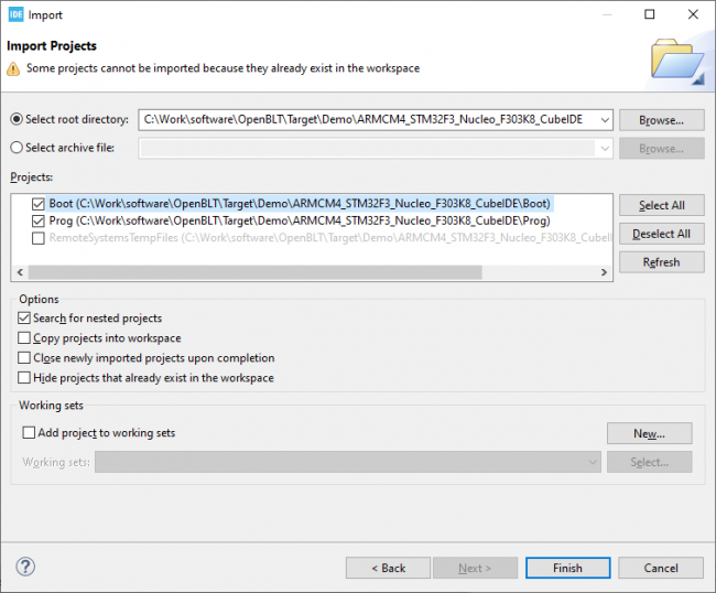
Open STM32CubeIDE and select the previous folder path\Demo as the Workspace.
-
File>import>General>Existing Project from Workspace
Once you have the project on the IDE you can modify the Boot program at your needs.
N.B If the main program need to use the external quartz clock the initialization must be made into the code not by modifying the .ioc confiuration, if this is done the openBLT will be overwritten.
Since multiple nodes are connected to the can-and the XCP protocol works on a point-to-point connection between Host and Target, this will update each node with the same program! we can avoid this with this additional procedure.
Let's take a look at the connect command that XCP use to connect to the Target:
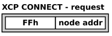
FFh it's ALWAYS 0xFF, meanwhile the second part (node addr) can be anything. The idea is to use this part as a node address to identify which node needs to be updated.
Modification needed:
-
Open the blt_conf.h configuration file
find this lines
#define BOOT_COM_CAN_ENABLE (1)
#define BOOT_COM_UART_ENABLE (1)
#define BOOT_FILE_SYS_ENABLE (1)
change these to:
#define BOOT_COM_CAN_ENABLE (1)
#define BOOT_COM_UART_ENABLE (0)
#define BOOT_FILE_SYS_ENABLE (0)
-
We need to make a node individually addressable, we will use what's called a "Hook function" called
XcpPacketReceivedHook()
-
First open blt_conf.h and insert this lines of code:
/**********************************************************************
*   X C P   C O M M U N I C A T I O N   C O N F I G U R A T I O N
**********************************************************************/
/** \brief Enable or disable the hook function that gets called each
 *         time an XCP packet was received from the host.
 */
#define BOOT_XCP_PACKET_RECEIVED_HOOK   (1)

/** \brief The second byte in the XCP connect command (connection mode)
 *         is used as a node address in the range 0..255. Configure the
 *         address of this specific node with this macro.
 */
#define BOOT_XCP_CONNECT_MODE_NODE_ADDR (3) //the number three is the address 											 //chosen, can be 0 to 255
done this, we have defined the address of the node.
-
-
Now we can implement the Hook Function
-
Go in the \App\Hook.c and add the hook function
/********************************************************************** * X C P C O M M U N I C A T I O N H O O K F U N C T I O N S **********************************************************************/ #if (BOOT_XCP_PACKET_RECEIVED_HOOK > 0) /******************************************************************//** ** \brief Callback that gets called when a new XCP packet was ** received from the host, before it got processed by the ** XCP communication module. ** \param data Pointer to byte buffer with packet data. ** \param len Number of bytes in the packet. ** \return BLT_TRUE is the packet was processed by this function, ** BLT_FALSE if the packet should be processed by the XCP ** protocol as usual. ** **********************************************************************/ blt_bool XcpPacketReceivedHook(blt_int8u *data, blt_int8u len) { blt_bool result = BLT_FALSE; /* Intercept the connect command which consists of two bytes with the * first byte always being 0xFF and the second byte being the * 'connection mode', which is used to pass on a node address in this * example. Only allow the connection to be established, if it is * addressed to us. * * ----------------------- * | 0xFF | node address | * ----------------------- * */ /* Is this the connect command, but not addressed to us? */ if ( (rxMsgData[0] == 0xFF) && (rxMsgHeader.DLC == 2) && (rxMsgData[1] != BOOT_XCP_CONNECT_MODE_NODE_ADDR) ) { /* Do not establish a connection simply by ignoring this connect * command. This is achieved by informing the XCP communication * module that this packet was fully processed by this function * and no further processing is needed by the XCP communication * module. */ result = BLT_TRUE; } /* Give the result back to the caller. */ return result; } /*** end of XcpPacketReceivedHook **/ #endif /* BOOT_XCP_PACKET_RECEIVED_HOOK > 0 */ -
Now rebuild the project
-
-
Finally Run so the code is loaded on the MCU.
Now we can take care of the Program, cause the Boot is done but since in the Program we have functions that detect firmware update we want to avoid useless boot start up. So we will modify this part by cheking the Node Address.
Open the \App\boot.c
Find this lines:
 /* check if this was an XCP CONNECT command  */
     if ((rxMsgData[0] == 0xff) && (rxMsgHeader.DLC == 2))
     {
       / * connection request received so start the bootloader */
       BootActivate();
     }
And change it to:
 /* check if this was an XCP CONNECT command * /
     if ((rxMsgData[0] == 0xff) && (rxMsgHeader.DLC == 2) && (rxMsgDat[1] == BOOT_XCP_CONNECT_MODE_NODE_ADDR))
     {
       /* connection request received so start the bootloader */
       BootActivate();
     }
Rebuild project.
Now that the bootloader is ready:
- delete the .elf file in Debug folder
- F5 to refresh the project
- Build project
- Debug and Resume
Now if the led blink fast, the bootloader is active.
-
Connect the nucleo or the wheel node to the can-bus
-
Connect LAWICEL CANUSB device in the pc (Download DRIVER)
-
In the repository path go to Host and open MicroBoot.exe
- First on settings, under Communication Interface, on interface selection choose XCP on CAN
- Under the voice communication choose Lawicel CANUSB
- IF multiple can is used under Session Protocol, the Mode stands for the Node Address
-
Now we can close this and choose what file we want to update, we have to choose the S-Record file.
Go to the demo path Prog\Debug\nome_file**.srec**
-
Now that the file is selected it will start on itself
Now we have both the user program and Bootloader in the flash memory.