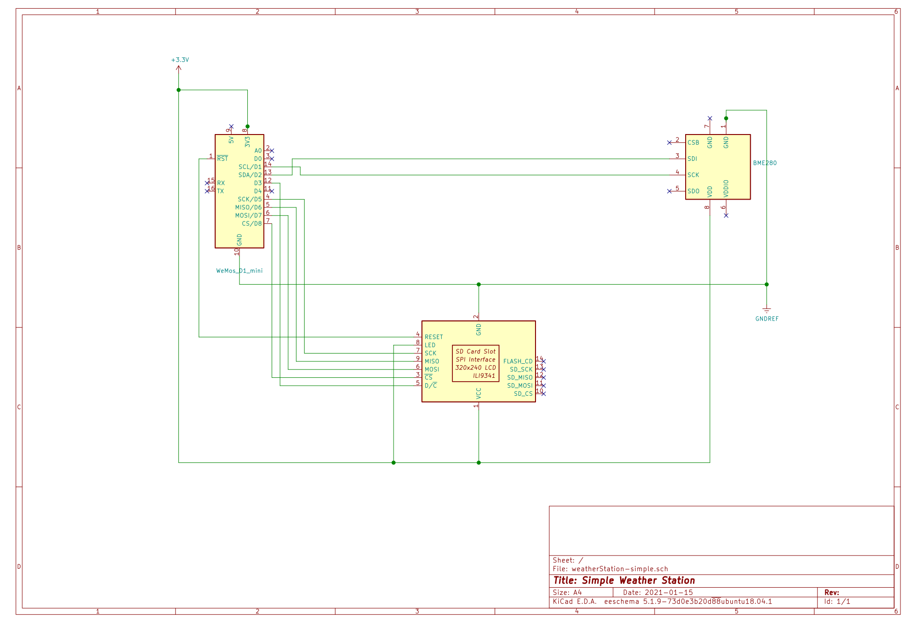
The TFT display is connected by SPI, and the sensor through I2C.
The TFT library used is https://github.com/Bodmer/TFT_eSPI
Wiring configuration was done with the indications of file /home/user/Arduino/libraries/TFT_eSPI/User_Setup.h :
// Display SDO/MISO  to NodeMCU pin D6 (or leave disconnected if not reading TFT)
// Display LED       to NodeMCU pin VIN (or 5V, see below)
// Display SCK       to NodeMCU pin D5
// Display SDI/MOSI  to NodeMCU pin D7
// Display DC (RS/AO)to NodeMCU pin D3
// Display RESET     to NodeMCU pin D4 (or RST, see below)
// Display CS        to NodeMCU pin D8 (or GND, see below)
// Display GND       to NodeMCU pin GND (0V)
// Display VCC       to NodeMCU 5V or 3.3V
// ###### EDIT THE PIN NUMBERS IN THE LINES FOLLOWING TO SUIT YOUR ESP8266 SETUP ######

// For NodeMCU - use pin numbers in the form PIN_Dx where Dx is the NodeMCU pin designation
#define TFT_CS   PIN_D8  // Chip select control
#define TFT_DC   PIN_D3  // Data Command control pin
#define TFT_RST  PIN_D4  // Reset pin (could connect to NodeMCU RST, see next line)

