Coder Social home page Coder Social logo

thekikgen / usbmidiklik Goto Github PK

View Code? Open in Web Editor NEW
87.0 11.0 17.0 864 KB

A robust USB MIDI Arduino firmware, with a dual bootloader, based on the LUFA library

C++ 44.16% C 47.30% Batchfile 0.72% Makefile 7.81%
usb midi converter dual bootloader firmware sysex arduino

usbmidiklik's Introduction

    __ __| |           |  /_) |     ___|             |           |
       |   __ \   _ \  ' /  | |  / |      _ \ __ \   |      _` | __ \   __|
       |   | | |  __/  . \  |   <  |   |  __/ |   |  |     (   | |   |\__ \
      _|  _| |_|\___| _|\_\_|_|\_\\____|\___|_|  _| _____|\__,_|_.__/ ____/

USBMidiKliK

A robust USB MIDI Arduino firmware, with a dual bootloader, based on the last version of the LUFA library.

Creative Commons License
This work is licensed under a Creative Commons Attribution-NonCommercial 4.0 International License.

If you are a regular user of USBMidiKlik, please consider making a donation to encourage our team, and to pay for the coffees swallowed during the long nights of coding !

Donate

As other project, like HIDUINO, or MOCOLUFA (thanks to them for inspiration), USBMIDIKLIK allows your Arduino board to become a very reliable MIDI IN/OUT USB interface. Despite the very good work done on these projects, i was facing some issues... An heavy MIDI traffic (sysex...) was blocking the serial, and some MIDI messages were purely ignored by the parser, like the song pointer position for example. More, these projects rely on a quite old version of the LUFA library.

USBMidiKliK uses interrupts and ring buffers to ensure that (fast) USB to (slow) midi transfers are reliable, plus a "more transparent as possible" midi parser. MIDI product device name is integrated in the makefile, and can also be modified by sysex, or a configuration menu...so easy to change.

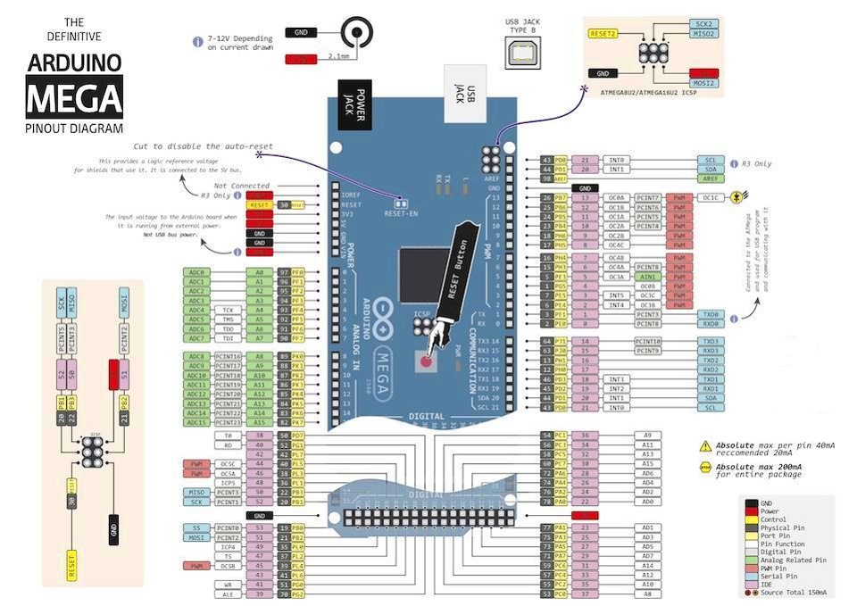
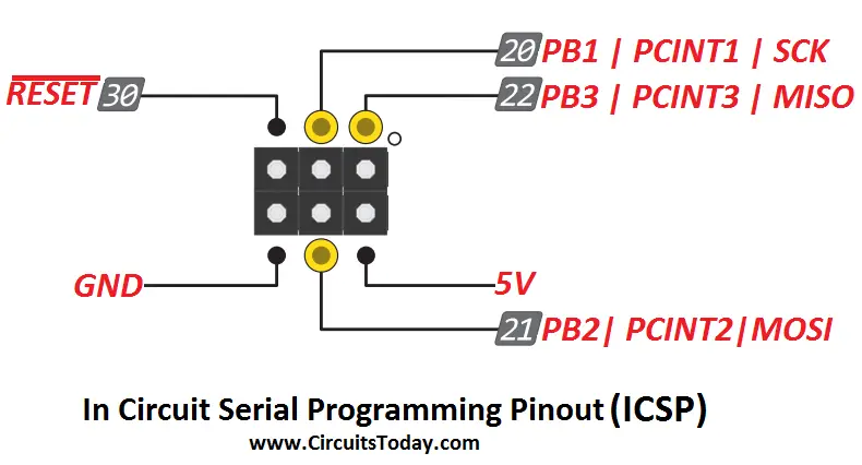
This firmware is uploaded in the ATMEGA8U2 chip managing the USB, and changes the default USB serial descriptors to the MIDI ones. For more convenience when updates are needed, a "dual mode" is embedded, allowing to switch back to the USB serial : when the PB2/MOSI pin of the ATMEGA8U2 is connected to ground, the Arduino is a classical one again, and you can change and upload a new firmware in the ATMEGA328P (UNO) with the standard Arduino IDE.

Obviously, it is also possible to upload this firmware to other members of the Arduino family, like the Arduino Micro for example.

With a Uno, in a "MIDI USB converter" mode, data flow are the following :

		     ----------- ARDUINO UNO ----------------------------------------
								   ATMEGA 328P
   USB                          ATMEGA8U2                        UART NOT ACTIVE
-------------         ------------------------------          ------------------------
IN Endpoint  o<-----o | USBOUT  (usbMidiKliK )  RX | o<-----o |  (TX) pinMode(INPUT) | o<-----  MIDI IN
OUT Endpoint o----->o | USBIN   ( firmware   )  TX | o----->o |  (RX) pinMode(INPUT) | o----->  MIDI OUT   

If you need USB to talk with external MIDI IN/OUT (with DIN jacks), the RX/TX on the ATMEGA328P must no be crossed, as the ATMEGA8U2 TX/RX are hardwired to these RX and TX pins on the Uno board. When PIN0 (RX on the Arduino board socket) and PIN1 (TX on the Arduino board) are configured as INPUT, external devices can talk directly with the ATMEGA8U2 managing the USB, making the Arduino UART transparent.

If your project is a pure USB MIDI controller, simply setup serial to 31250 bauds in your sketch, to receive and send from/to MIDI application on the host side. In that configuration, you can still have an external MIDI-OUT jack connected to TX, but UART RX will be dedicated to USB. You can eventually use the SoftwareSerial library to get a MIDI IN on another pin, if your MIDI traffic is light.

                                                                   ATMEGA 328P
       USB                           ATMEGA8U2                     UART ACTIVE
   -------------         ------------------------------          --------------
   IN Endpoint  o<-----o | USBOUT  (usbMidiKliK )  RX | o<-----o |     (TX)   | o----->  MIDI OUT   
   OUT Endpoint o----->o | USBIN   ( firmware   )  TX | o----->o |     (RX)   | X NOT POSSIBLE <-----  MIDI IN

TTL/Serial MIDI IN and MIDI OUT conversion schematics can be found easily on the web.

System Exclusive messages

Sysex have the following format :

F0 <USB MidiKlik sysex header = 0x77 0x77 0x77> <sysex function id > <data > F7

Serial Configuration menu Bootmode (function 0x08)

This sysex enables the configuration menu accessible from the USB serial. Immediatly after sending this sequence, the interface reboots in CDC serial COM mode, allowing you to open a terminal to configure easily USBMIDIKLIK.

 F0 77 77 77 08 F7

The following menu should appear after pressing ENTER :

 USBMIDIKliK                                                                     
 (c)TheKikGen Labs                                                               

 0.Show current settings                                                         
 1.Reload settings                                                               
 2.Product string                                                                
 3.VID - PID                                                                     
 4.Channel mapping                                                               
 5.Default channel mapping                                                       
 a.Arduino mode                                                                  
 s.Save & quit                                                                   
 x.Abort                                                                         
 =>s  

Temporary boot in Arduino serial mode (0x09)

If you need to update the Arduino firmware without positionnig a jumper, you can you cand send this sysex that will reboot the device in serial mode, until the next boot.

 F0 77 77 77 09 F7

Hardware reset (0x0A)

To avoid unplugging the USB cable, you cand send this sysex that will do an harware reset programatically. The full Arduino board will be resetted (ATMEGA8U2 USBMidiKliK firmware + ATMEGA328P and sketch firmware). The sysex message structure is the following :

   F0 77 77 77 0A F7

For example to set ProductString, VendorID, Product ID and restart the USB Midi interface with new data, send the following sysex :

  F0 77 77 77 0B 55 53 42 20 4D 69 64 69 4B 6C 69 4B F7
  F0 77 77 77 0C 08 0F 01 02 09 00 06 07 F7
  F0 77 77 77 0A F7

Changing the device ProductStringName (0X0B)

It is possible to change the USB device ProductStringName via a SYSEX or from the configuration menu. The new name is saved in the ATMEGA8U EEPROM, so it persists even after powering off the Arduino. The message structure is the following :

   F0 <USB MidiKlik sysex header = 0x77 0x77 0x77> <sysex function id = 0x0b> <USB Midi Product name > F7

The following SYSEX sent from an Arduino sketch will change the name of the MIDI interface to "USB MidiKliK" :

   F0 77 77 77 0B 55 53 42 20 4D 69 64 69 4B 6C 69 4B F7

The product name is limited to 30 characters max, non accentuated (ascii code between 0 and 0x7F).

Example code you can use in your Arduino sketch :

// NB : Setting Product string will reboot the ATMEGA8U and the Arduino

  // Send SYSEX Message # 0B
  Serial.write( 0xF0 );
  Serial.write( 0x77 );
  Serial.write( 0x77 );
  Serial.write( 0x77 );
  Serial.write( 0x0B );

  // Important : do not use accentuated characters to avoid 8 bits values
  char * ProductString = "USB MIDI Demo";

  for (uint8_t i=0; *(ProductString + i ) !=0 ; i++ ) {
     Serial.write(* ( ProductString + i ) );
  }

  Serial.write( 0xF7 );     

Changing the USB VendorID and ProductID (0x0C)

In the same way, you can also change the USB Vendor and Product Ids with a SYSEX. They are also saved in the ATMEGA8U EEPROM after an update and persist after power off. The sysex message structure is the following :

F0 77 77 77 <func id = 0x0C> <n1n2n3n4 = Vendor Id nibbles> <n1n2n3n4 = Product Id nibbles> F7

As MIDI data are 7 bits bytes, we must use a special encoding, to handle VendorId and ProductID beeing 16 bits values. To stay light, and because the message is very short, 2 x 16 bits values, the encoding will consists in sending each nibble (4 bits) serialized in a bytes train. For example sending VendorID and ProductID 0X8F12 0X9067 will be encoded as :

  0x08 0XF 0x1 0x2  0X9 0X0 0X6 0X7

so the complete SYSEX message will be :

  F0 77 77 77 0C 08 0F 01 02 09 00 06 07 F7

Example of an Arduino code you can use in a sketch :

      void setVendorProductIds(uint16_t vendorID,uint16_t productID) {

            Serial.begin(31250);

            // Send SYSEX Message # 0C
            Serial.write( 0xF0 );
            Serial.write( 0x77 );
            Serial.write( 0x77 );
            Serial.write( 0x77 );
            Serial.write( 0x0C );

            Serial.write( (vendorID & 0xF000)  >> 12 );
            Serial.write( (vendorID & 0x0F00)  >> 8  );
            Serial.write( (vendorID & 0x00F0)  >> 4  );
            Serial.write(  vendorID & 0x000F );

            Serial.write( (productID & 0xF000)  >> 12 );
            Serial.write( (productID & 0x0F00)  >> 8  );
            Serial.write( (productID & 0x00F0)  >> 4  );
            Serial.write(  productID & 0x000F );

            Serial.write( 0xF7 );        
            resetMidiUSB();
      }

Define a new midi channel mapping (0xD)

It is possible to remap a midi channel to one or many other channels, when you need to change, for example, static midi channels in an equipment. The sysex message structure is the following :

 F0 77 77 77 <sysex function id = 0x0D> <Midi IN channel> <n bytes Midi OUT targets> F7

or

F0 77 77 77 <sysex function id = 0x0D> <Midi IN channel> <MUTE = 0x00 | DEFAULT = 0x7F> F7

Midi IN and Targets midi OUT channels are passed as bytes from 1 to 16 (0x01 to 0x10). You can pass a variable number of MIDI OUT channels, but 16 as a maximum.

Passing 0x00 immediatly after the MIDI IN byte will "mute" the channel. Passing 0x7F will reset all the mapping to default. Default is 1=>1, 2=2,....16=>16

For example, to map the midi channel 2 to channel 2,5 and 16, map the channel 3 to channel 4, and mute the channel 16, send the SYSEX MESSAGES :

	F0 77 77 77 0D 02 02 05 10 F7
	F0 77 77 77 0D 03 04 F7
	F0 77 77 77 0D 10 00 F7

How to compile the firmware

  1. You must have the WINAVR or gcc-avr installed on your computer.

sudo apt-get install gcc-avr binutils-avr avr-libc gdb-avr avrdude

  1. Clone the USBMidiKlik source code and its submodules lufa and midiXparser :

git clone --recurse-submodules https://github.com/TheKikGen/USBMidiKliK

  1. To build for uno, use 'make uno'.

To get help, use 'make mdkhelp'.

usbmidiklik's People

Contributors

thekikgen avatar

Stargazers

 avatar  avatar  avatar  avatar  avatar  avatar  avatar  avatar  avatar  avatar  avatar  avatar  avatar  avatar  avatar  avatar  avatar  avatar  avatar  avatar  avatar  avatar  avatar  avatar  avatar  avatar  avatar  avatar  avatar  avatar  avatar  avatar  avatar  avatar  avatar  avatar  avatar  avatar  avatar  avatar  avatar  avatar  avatar  avatar  avatar  avatar  avatar  avatar  avatar  avatar  avatar  avatar  avatar  avatar  avatar  avatar  avatar  avatar  avatar  avatar  avatar  avatar  avatar  avatar  avatar  avatar  avatar  avatar  avatar  avatar  avatar  avatar  avatar  avatar  avatar  avatar  avatar  avatar  avatar  avatar  avatar  avatar  avatar  avatar

Watchers

 avatar  avatar  avatar  avatar  avatar  avatar  avatar  avatar  avatar  avatar  avatar

usbmidiklik's Issues

Arduino Uno not detected on USB bus after flashing

Successfully flashed the 16u2 on an Arduino Uno R3 clone (Elegoo), but after disconnecting the ISP programmer and unplugging/reconnecting the USB cable to the Uno, the device was not detected on the USB bus.

It wasn't just unrecognized or reported as malfunctioning, Windows 10 didn't detect that a new USB device had been plugged in. (This happened both with and without a jumper across ISP pins 4/6.)

Note: The same steps using 'mocolufa' works for me, leading me to believe it's a bug or incompatibility with USBMidiKliK as opposed to user error.)

> .\avrdude.exe -c usbtiny -P usb -p m16u2 -b 19200 -U flash:w:USBMidiKliK_dual.hex:i

avrdude.exe: AVR device initialized and ready to accept instructions

Reading | ################################################## | 100% 0.03s

avrdude.exe: Device signature = 0x1e9489 (probably m16u2)
avrdude.exe: NOTE: "flash" memory has been specified, an erase cycle will be performed
             To disable this feature, specify the -D option.
avrdude.exe: erasing chip
avrdude.exe: reading input file "USBMidiKliK_dual.hex"
avrdude.exe: writing flash (8644 bytes):

Writing | ################################################## | 100% 10.57s

avrdude.exe: 8644 bytes of flash written
avrdude.exe: verifying flash memory against USBMidiKliK_dual.hex:
avrdude.exe: load data flash data from input file USBMidiKliK_dual.hex:
avrdude.exe: input file USBMidiKliK_dual.hex contains 8644 bytes
avrdude.exe: reading on-chip flash data:

Reading | ################################################## | 100% 7.27s

avrdude.exe: verifying ...
avrdude.exe: 8644 bytes of flash verified

avrdude.exe: safemode: Fuses OK (E:F4, H:D9, L:FF)

avrdude.exe done.  Thank you.

midi Data[0] incorrect when send Program Change

when i try to send a PC message it sends last sent Data byte in midi data[0].
Step to reproduce:

  1. send midi CC 34 value 44 on channel 5 OK
  2. try to send ProgramChange 12 on channel 5 -> it sends midi PC 44 on channel 5

with hiduno works. (hiduno has problem with PC inputs instead USBMidiKliK works great!)

Arduino Mega?

Hey!

How can I use the firmware with a Arduino Mega?
So far I have been using the version for Uno.
This works, somehow.
But when I turn the device into USB serial mode, the device is recognized as an Arduino Uno, which leads to difficulties.

Is there a simple solution?

Missing Bytes on SysEx

For some reason my code sending SysEx is missing bytes, this seems to happen when sending 6 bytes, but not 7

    stream.write( 0xF0 );
    stream.write( 0x7F );
    stream.write( 0x7F );
    stream.write( 0x06 );
    stream.write( 0x02 );
    stream.write( 0xF7 );
522653696: 0xf07f7ff7
    stream.write( 0xF0 );
    stream.write( 0x7F );
    stream.write( 0x7F );
    stream.write( 0x06 );
    stream.write( 0x02 );
    stream.write( 0x02 );
    stream.write( 0xF7 );
527349760: 0xf07f7f060202f7

Please change to an open source license

CC-NC is not remotely an open source license by OSI standards, and it is also not a license designed for nor appropriate for source code. It was made for other kinds of media, and does not contain verbage appropriate for source code. Creative Commons itself strongly warns against using CC licenses, especially NC, for code; and FSF also says that they are very bad.

At least it's not CC-SA-NC, which is in fact incompatible with Arduino's own LGPL license...

I understand the desire to prevent companies from using your code, though by doing so violates open source standards. The nearest thing philosophically is probably GPL: companies can use your code in house, but they can't sell anything that uses it without giving back. I would ask that you change to at least GPL 3.

Go into "dual mode" using an Arduino Mega (ATmega16U2)

Hi,

First, thank you for your hard work. The firmware works perfectly for me -- I managed to build it for the Mega using EsGeh's pull request.

I'd like to use the dual mode advertised in the README:

For more convenience when updates are needed, a "dual mode" is embedded, allowing to switch back to the USB serial : when the PB2/MOSI pin of the ATMEGA8U2 is connected to ground, the Arduino is a classical one again, and you can change and upload a new firmware in the ATMEGA328P (UNO) with the standard Arduino IDE.

However, I can't seem to achieve that. I tried both the following bridging (reference in links): GND to Digital 51, GDN to ICSP PB2. None of them produced the expected result.

Am I missing something?

Thanks!

build instructions

Would be nice to have a few lines how to build the bootloader, for unexperienced users like me.
(naively typing make leads to an error because of hardcoded windows (!) path...)

Error: unrecognized command line option

Hi,

When trying to make I get the error:

cc1plus.exe: error: unrecognized command line option "-std=gnu++11"

Environment is Windows 7 64bits with WinAVR 2010-01-20 (latest available version from SourceForge).

Is this a problem with the gcc version of WinAVR? How to troubleshoot this issue?

Thanks!

Assistance needed for enhancement

First of all thank you for this extremely solid piece of work.

I wonder if you (or some other kind soul) can help a beginner out with an custom enhancement. I hope it's ok to open an issue for questions like this, if not, please just close it.

What I want to do, is to add an analog pin listener to USBMidiKliK. When the value of any of 4 potentiometers change, the value should be mapped to MIDI CC controller 1-4 values 0-127, put in a neat midiPacket_t, inserted into the ring buffer and shipped to Serial or USB.

I made some tweaks to naught101/midi_knobs/midi_knobs.ino and now the general logic works as I need it to, but I need guidance how to correctly implement it in the USBMidiKlik architecture.

I have integrated the modified naught101 code, and added an #include wiring_analog.c (probably a completely backwards way to do this include :/ ) to be able to utilize the analogRead() function, from the AVR Core (ArduinoCore-avr-master), and I basically added the following code to USBMidiKlik_dual.cpp:

///////////////////////////////////////////////////////////////////////////////
// PROCESS POTMETER TO SERIAL/USB
// ----------------------------------------------------------------------------
// Check whether any potmeters has changed
///////////////////////////////////////////////////////////////////////////////

#include "wiring_analog.c"
#define N_POTS 1

const uint8_t MIDICC = 0x0B;

const int potPins[] = {0, 1, 2, 3};
const uint8_t potCC[] = {0x0A, 0x0B, 0x0C, 0x0D};

uint8_t potVals[N_POTS];
uint8_t potValsPrev[] = {0, 0, 0, 0};

static int map(int x, int x1, int x2, int y1, int y2){
return (x - x1) * (y2 - y1) / (x2 - x1) + y1;
}

static void SendCC(byte channel, byte control, byte value){
MIDI_EventPacket_t MIDIEvent = {0x0B, 0xB0 | channel, control, value};
RoutePacketToTarget(FROM_USB, (midiPacket_t *)&MIDIEvent);
RoutePacketToTarget(FROM_SERIAL, (midiPacket_t *)&MIDIEvent);
}

static void ProcessPots(){
for (int i=0;i<N_POTS;i++) {
if (abs(potValsPrev[i] - potVals[i]) > 1)
{
SendCC(0, potCC[i], potVals[i]);
potValsPrev[i] = potVals[i];
}
}
}

static void ReadPots(){
for (int i=0; i < N_POTS; i++) {
int val = analogRead(potPins[i]);
int mval = (uint8_t)(map(val, 0, 1023, 0, 127));
potVals[i] += (mval - potVals[i])/4;
}
}

///////////////////////////////////////////////////////////////////////////////

I then tried to find where to properly hook it up, and i ended up adding calls to ReadPots() and ProcessPots() in the infinite loop in ProcessMidiUSBMode() which seemed most suitable.

for ( ;; ) {
...
ProcessMidiToUsb();
ProcessUsbToMidi();
ReadPots();
ProcessPots();

MIDI_Device_USBTask(&Keyboard_MIDI_Interface);
USB_USBTask();
}

Much to my surprise my changes actually compiles, but as very much expected, operating the CC potentiometer on my breadboard does not seem to send any MIDI. The Pro Micro still presents itself to my laptop as a USBMidiKlik device, so I do not believe I have completely broken the code, but my own changes do not work.

I think my first, very basic question on this long story is, if my approach to creating sending off the CC midi packages using RoutePacketToTarget, is anywhere near the correct solution for the task at hand, assuming the CC logic is working.

script not working

Sorry if this is the wrong place but I cannot get this script working on. OSX:
#7

I have fish v3.40 install from homebrew, so the only thing I have changed is the fish path in init.fish to:
/usr/local/bin/fish

The script runs but produces the following error:

./scripts/init.fish readlink: illegal option -- m usage: readlink [-n] [file ...] usage: dirname path readlink: illegal option -- m usage: readlink [-n] [file ...] usage: dirname path mkdir: /dependencies: Read-only file system ERROR while downloading 'https://github.com/EsGeh/git_deps/raw/755daa23dd0b17cc986d4a1339e93ef5ec621fc7/get_deps.fish'

Any help appreciated
TIA

usb host

Does this scheme work as a usb host?

The proper way to upload the bootloader on the ATmega16u2

Hello,
I have sent you a message on your personnal blog, I tried to compile your project to the ATmega 16u2 chip, but I can't find the proper way to upload it (or even compile it). Do you have a schema of connections, a way of doing that properly, or a tutorial for a similar project that also work on yours ?

Thanks a lot

HEX file

Hello! Best regards from Chile.

Well this is not an issue at all... I would like to ask for help. Is there a way that you could upload a build hex file? I Don't know how to compile it.

I know it has to be made using WINAVR or withina avr-gcc environment that I don't know how to execute since I usually only work with arduino IDE.

Hope you can helpme or maybe explain me how to do it. Thanks so much Sr.

I would like to upload it to an ATMEGA16U2 on my Arduino Uno... But also, on a near future, i would like to buy standalone's atmegas16U2... could i upload this firmware just by USB (obiusly, building the circuit posted on your schematic). Mi idea is to use it to interface USB MIDI on a STM32F401. Thanks!

I do not know how to generate Mega hex file

Hi and thank you for your code.
I made a Jupiter-8 (Arturia plugin) controller over a MEGA. Everything works fine when I tried your software over an UNO (reset Arduino, Atmel Flip, etc) but now, i have to inject it over the MEGA and I do not know how can i do it. I do not have hex file for MEGA and I do notknow how compilate it. I read #8 post and I spent half of the morning figuring out the way to do it, but I am not capable. Is it a process involving the command line? I am a newby in programing. Thank you

Changing device name

Hi,

First i want to thank you for all your work, it's great !!

I tried to change the name of the midi device without success.
the name is stuck to USA MidiKliK Build-646

  • I edit the makefile and build a new .hex file (i see -DMIDI_DEVICE_PRODUCT_STRING="USA Miditest Build-654 " in compilation log)

  • I connect my Arduino Uno R3 in DFU mode and upload the new .hex file with

    sudo dfu-programmer atmega16u2 erase
    dfu-programmer atmega16u2 flash USBMidiKliK_dual.hex
    dfu-programmer atmega16u2 reset

  • I disconnect / reconnect the Arduino but the name is still USA MidiKliK Build-646

  • I tried to upload the sketch midiUsbConverter.ino and call SetProductString() in the setup()

  • I tried to use the OSX app SysExLibrarian (https://www.snoize.com/SysExLibrarian/) to upload the sysex of your readme (F0 77 77 77 0B 55 53 42 20 4D 69 64 69 4B 6C 69 4B F7) and reboot the Arduino

In all cases, device name is still "USA MidiKliK Build-646"

Do you have any idea of what is causing this ? Thanks you very much for you help

Dual boot mode on the Uno (R3)

Hi, nice project.

Can you please clarify how the dual boot function is supposed to work? It looks like MISO is on pin 12/PB4, not PB2.
https://www.circuito.io/blog/arduino-uno-pinout/

I tried to shorting this pin to ground whilst attaching USB connection (to power board), but it remained as Midi-Kik device. I had flashed the pre-build firmware from git.

$ lsusb
Bus 002 Device 001: ID 1d6b:0003 Linux Foundation 3.0 root hub
Bus 001 Device 005: ID 0cf3:e301 Atheros Communications, Inc. 
Bus 001 Device 004: ID 187c:0527 Alienware Corporation 
Bus 001 Device 003: ID 0c45:6708 Microdia 
Bus 001 Device 075: ID 2912:1967  <------------------------------------ no change
Bus 001 Device 001: ID 1d6b:0002 Linux Foundation 2.0 root hub
$ aconnect -l
client 0: 'System' [type=kernel]
    0 'Timer           '
    1 'Announce        '
	Connecting To: 129:0
client 14: 'Midi Through' [type=kernel]
    0 'Midi Through Port-0'
client 20: 'USB MidiKliK Build-646' [type=kernel,card=1]
    0 'USB MidiKliK Build-646 MIDI 1'
client 128: 'bridge' [type=user,pid=9971]
    0 'playback

Arduino Mega send-receive via USB and MIDI DIN

Hello...I have an Arduino Mega and I want it to send and receive midi via USB....that works very well...according to what I read, this firmware can send messages via Midi Din Out at the same time

But I don't understand how to be able to receive via Midi Din In and send that message via USB Out.
I would like to know if this can be enabled at runtime.

My other question is...can I disable Midi Din Out at runtime?

I hope you can understand me

Thank you very much for your work
Greetings

Could you please add a compiled HEX for mega?

I tried compiling by myself following the wiki but no luck.
Could you please add a compiled version of the firmware for arduino mega?

Thank you for sharing this project

All the best

Digitally controlled firmware state rather than physical

Hi!

I'm wanting to switch between firmware's based on a command i can send to the 16u2.
So normally it shows up as a midi controller but when i hit "Update" on my custom avrdude program it switches the firmware on the 16u2 and then updates my 4809 to the latest code and then switches back to the midi firmware.
is this doable with your code?

Recommend Projects

  • React photo React

    A declarative, efficient, and flexible JavaScript library for building user interfaces.

  • Vue.js photo Vue.js

    ๐Ÿ–– Vue.js is a progressive, incrementally-adoptable JavaScript framework for building UI on the web.

  • Typescript photo Typescript

    TypeScript is a superset of JavaScript that compiles to clean JavaScript output.

  • TensorFlow photo TensorFlow

    An Open Source Machine Learning Framework for Everyone

  • Django photo Django

    The Web framework for perfectionists with deadlines.

  • D3 photo D3

    Bring data to life with SVG, Canvas and HTML. ๐Ÿ“Š๐Ÿ“ˆ๐ŸŽ‰

Recommend Topics

  • javascript

    JavaScript (JS) is a lightweight interpreted programming language with first-class functions.

  • web

    Some thing interesting about web. New door for the world.

  • server

    A server is a program made to process requests and deliver data to clients.

  • Machine learning

    Machine learning is a way of modeling and interpreting data that allows a piece of software to respond intelligently.

  • Game

    Some thing interesting about game, make everyone happy.

Recommend Org

  • Facebook photo Facebook

    We are working to build community through open source technology. NB: members must have two-factor auth.

  • Microsoft photo Microsoft

    Open source projects and samples from Microsoft.

  • Google photo Google

    Google โค๏ธ Open Source for everyone.

  • D3 photo D3

    Data-Driven Documents codes.