Coder Social home page Coder Social logo

t-edson / picpas Goto Github PK

View Code? Open in Web Editor NEW
87.0 22.0 27.0 169.53 MB

Compilador en Pascal para microcontroladores PIC / Pascal compiler for PIC microcontrollers

License: GNU General Public License v2.0

Pascal 99.64% C 0.36% C++ 0.01%
pascal-compiler pic-microcontroller

picpas's Introduction

Donate to the project

paypal

PicPas 0.8.8

Multi-platform Pascal cross-compiler for Microchip 8 bits PIC microcontrollers.

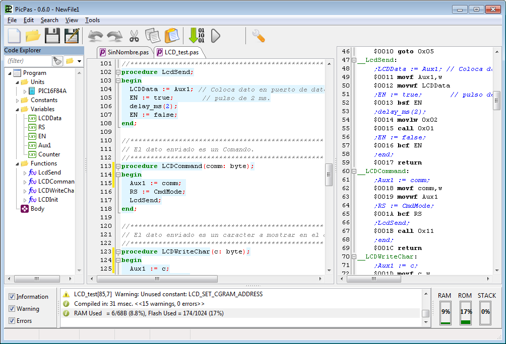
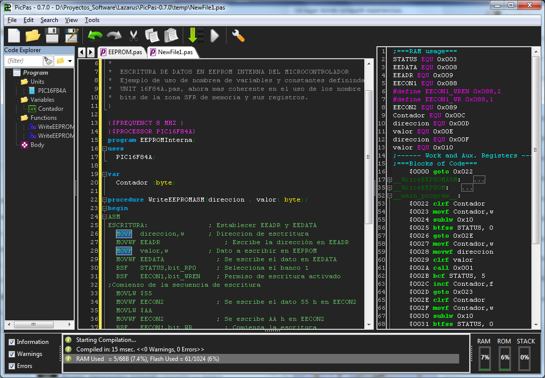
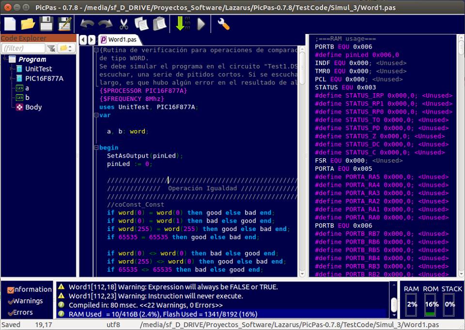
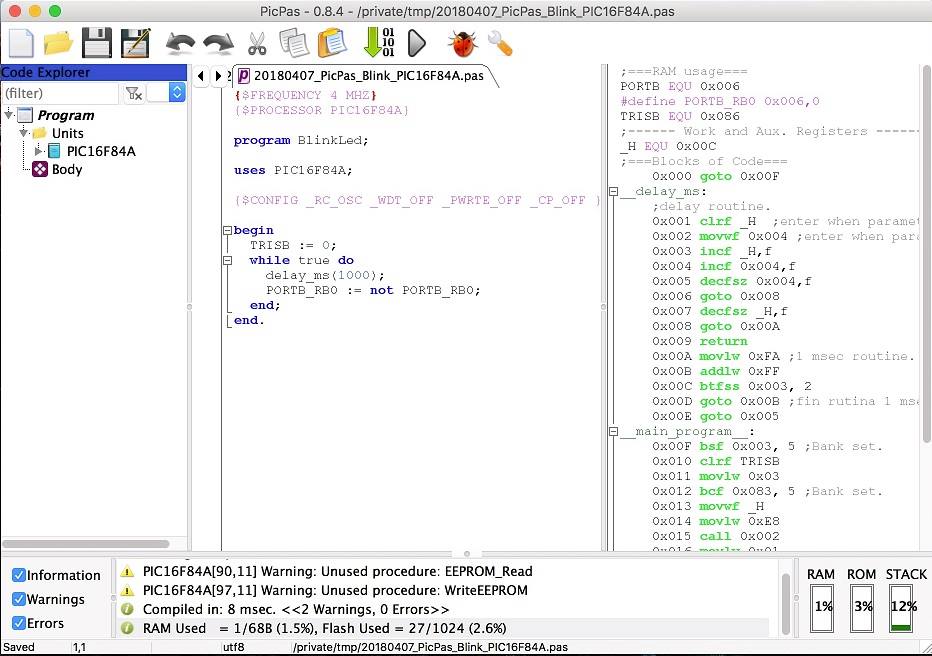
PicPas IDE

PicPas is a Pascal compiler and IDE, written in Lazarus, which generates executable code for Baseline and Mid-range PIC microcontrollers.

No additional libraries or software required to compile. PicPas generates the *.hex file directly.

PicPas works with a simplified version of the Pascal language, that has been adapted to work with limited resources small devices.

Currently, it only supports basic types.

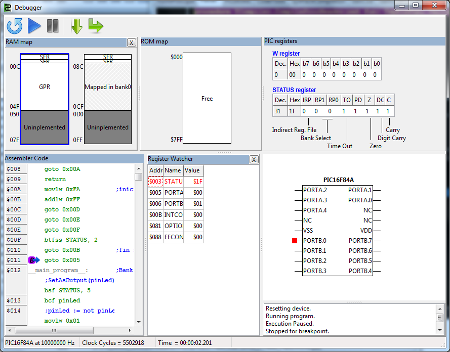
It includes a complete IDE/debugger/simulator to facilitate the development.

The PicpPas compiler includes advanced optimization options so the code obtained is generally more compact than the obtained with other compilers.

Installation

PicPas doesn't need installation, and have not dependencies, except the commons of the operative system, where it's runnig.

To run, it's only needed to download the folder from GitHub. There is compiled binaries for Windows-64 version (PicPas-win64.exe), Ubuntu version (PicPas-linux) and a Mac version (PicPas-Mac.dmg).

If it's required other platform, it need to be compiled from the source code.

When starting, PicPas could generate warning messsages, if not needed folders exist.

Hello World

As an example the following code, is to blink a LED on port B:

{Sample program to blink a Led on PORTB.7}
program BlinkLed;
uses PIC16F84A;
{$FREQUENCY 8MHZ}
var
  pin: bit absolute PORTB.7;
begin                          
  TRISB := 0;   //all outputs
  while true do 
    delay_ms(1000);
    pin := not pin;
  end;
end.

The processor target is defined including the correspondent unit in the USES section.

The CPU clock is defined using the directive {$FREQUENCY } and must be after the USES section.

Devices supported

Almost all the Mid-range and Baseline PIC devices are supported:

BASELINE DEVICES:

PIC10F200 PIC10F200 PIC10F202 PIC10F204 PIC10F206 PIC10F220 PIC10F222

PIC12F508 PIC12F509 PIC12F510 PIC12F519

PIC16F505 PIC16F506 PIC16F526 PIC16F527 PIC16F54 PIC16F57 PIC16F59

MID-RANGE DEVICES:

PIC10F320 PIC10F322

PIC12F609 PIC12F615 PIC12F617 PIC12F629 PIC12F635 PIC12F675 PIC12F683 PIC12F752

PIC16F73 PIC16F74 PIC16F76 PIC16F77 PIC16F83 PIC16F84 PIC16F87 PIC16F88

PIC16F610 PIC16F616 PIC16F627 PIC16F627A PIC16F628 PIC16F628A PIC16F630 PIC16F631 PIC16F636 PIC16F639 PIC16F648A PIC16F676 PIC16F677 PIC16F684 PIC16F685 PIC16F687 PIC16F688 PIC16F689 PIC16F690

PIC16F707 PIC16F716 PIC16F720 PIC16F721 PIC16F722 PIC16F722A PIC16F723 PIC16F723A PIC16F724 PIC16F726 PIC16F727 PIC16F737 PIC16F747 PIC16F753 PIC16F767 PIC16F777 PIC16F785

PIC16F818 PIC16F819 PIC16F870 PIC16F871 PIC16F872 PIC16F873 PIC16F874 PIC16F874A PIC16F876 PIC16F877 PIC16F882 PIC16F883 PIC16F884 PIC16F886 PIC16F887

PIC16F913 PIC16F914 PIC16F916 PIC16F917 PIC16F946

Support are implemented using units. So if we need compile to the PIC16f628A, we write:

program anything;
uses PIC16F628A; 
begin
  ...
end. 

There is not yet support for Enhanced Mid-range, or the PIC18 High-preformance families of PIC.

IDE

PicPas includes an IDE integrated to the compiler, to help on developing the programs.

Some features of the IDE are:

• Cross-platform.

• Multiple editors windows.

• Syntax highlighting, code folding, word, and line highlighting for Pascal and ASM.

• Code completion, and templates for the common structures IF, REPEAT, WHILE, …

• Shows the assembler code and the resources used.

• Support for themes (skins).

• Code tools for completion and navigation.

• Check syntax in REAL TIME!!!.

• Several setting options.

• Translated to english, french, spanish and german.

Tito's Terminal

Tito's Terminal

Tito's Terminal

Debugger/Simulator

PicPas includes a graphical debugger/simulator for instructions of the Mid-Range core:

Tito's Terminal

To control the execution, the following keys can be used:

F5 -> Set a breakpoint in the current position of the assembler code. F6 -> Reste the device. F7 -> Step by step into subroutine. F8 -> Step by step over subroutine. F9 -> Run the program in real time.

Optimization Comparison

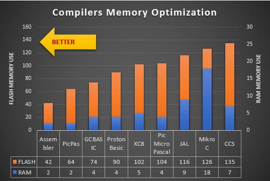
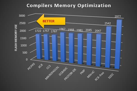
PisPas has been compared in two code optimization competition against the best profesional compilers for PIC microcontrollers, obtaining the first place in both.

Firts competition

Compiling a simple light sequence: https://github.com/AguHDz/PicPas-Librerias_y_Programas/tree/master/Comparacion%20PicPas-Otros%20Compiladores

Result:

Tito's Terminal

Second competition

Compiling a digital clock using I2C and the DS1307: https://www.facebook.com/groups/electronicaymicrocontroladores/permalink/1812269192135162/

Result

Tito's Terminal

Language Reference

Program structure

program <Name>;  //optional
uses
  //Units declarations

const
  //Constants declarations

var
  //Variables declarations

//<Procedures declaration>

begin
  //Main program body
end.

Unit structure

unit <name>;
interface
uses
  //units declaration
const
  //Constant declaration
var
  //Variable declaration

//Procedures declaration

implementation

uses
  //units declaration
const
  //Constant declaration
var
  //Variable declaration

//Procedures implementation

end.

Operators

Operator            Precedence
=================== ==========
 NOT, sign “-“         6
 *, DIV, MOD, AND      5
 +, -, OR, XOR         4
 =, <>, <, <=, >, >=   3
 := +=                 2

Types

Type           Size
============== ==========
 bit           1 bit
 boolean       1 bit
 byte          1 byte
 char          1 byte
 word          2 bytes
 dword         4 bytes

Numerical types are all unsigned.

Variables

Variables are defined with the VAR keyword:

var
  var1 : byte;
  var2 : bit;
  large_name_variable: boolean;

Variables can be defined too, at an absolute memory address:

var
  PORTB: BYTE absolute $06;
  pin0: bit; absolute $06.0;
  pin1: boolean; absolute PORTB.bit1;

Bit access can be performed too, using fields:

  var_byte.bit0 := 1;
  var_byte.bit7 := 0;

Specific byte of a word, can be access using fields:

  word_var.Low := $ff;
  word_var.High := $ff;

Control structures

PicPas doens't follow the common Pascal syntax. Instead, a new Modula-2, style syntax is implemented.

The common control structures have the following forms:

IF <condition> THEN 
  <block of code>
END;

IF <condition> THEN 
  <block of code>
ELSE
  <block of code>
END;

IF <condition> THEN 
  <block of code>
ELSIF <condition> THEN 
  <block of code>
ELSE
  <block of code>
END;

WHILE <condition> DO
  <block of code>
END;

REPEAT
  <block of code>
UNTIL <condition>;

FOR  <variable> := <start-value> TO <end-value> DO 
  <block of code>
END;

System Functions

System functions are always available in code. They don't need to be defined or included in a unit.

FUNCTION       DESCRIPTION
============== =================================================
delay_ms()	   Generate a time delay in miliseconds, from 0 to 65536.
Inc()          Increase a variable.
Dec()          Decrease a varaible.
SetBank()      Set the current RAM bank.
Exit()         Exit from a procedure or end the program.
Ord()          Convert a char to a byte.
Chr()          Convert a byte to a char.
Bit()          Convert an expression to a bit expression.
Byte()         Convert an expression to a byte expression.
Word()         Convert an expression to a word expression.
DWord()        Convert an expression to a dword expression.
SetAsInput()   Set a 8-bits port or a pin as an input.
SetAsOutput()  Set a 8-bits port or a pin as an output.

Procedure and Functions

PicPas use the Modula-2 syntax for procedures and functions:

Proedures are declared in the common Pascal syntax:

  procedure proc2(par1: byte);
  begin
    if par1 = 0 then 
      exit;
    else
      par1 := 5;
    end;  
  end;

Functions are declared the same, but indicating the type to return:

procedure TheNext(par1: byte): byte;
begin
  exit(par1 + 1);
end;

The return value is indicated with the exit() instruction.

When using in procedures parameters, a REGISTER parameter can be included:

procedure QuickParameterProc(register regvar: byte);
begin
  //Be carefull if put some code here
  PORTB := regvar;
end;

REGISTER parameters are fast, because they use the W register, so only one REGISTER parameter can be used. As REGISTER parameter is stored in W register, any operation using the W register, could lose its value, so the first operation in a procedure, using a REGISTER parameter must be read this parameter.

Interrupts

To manage interrupts, PicPas let us to define a special kind of Procedure:

  procedure My_ISR; interrupt;
  begin

    //ISR code

  end;

The name of the procedure is not important, but the declaration must be followed but the reserved word INTERRUPT.

Only one INTERRUPT procedure is allowed in a program.

When PicPas compile an INTERRUPT procedure, some special criterias are considered:

  1. Are always compiled starting in the address 0x0004.
  2. A RETFIE instruction is added to the end of the routine.
  3. No additional bank switching instructions are generated at the beginning of the procedure. It is the responsibility of the programmer to properly handle the banks within the routine.

INTERRUPT procedures don't save the value of registers or the control flags. This should be done manually.

ASM blocks

PicPas have a complete support for inserting ASM code inside the Pascal source.

ASM blocks must be included between the delimiters ASM and END:

procedure DoSomething;
begin
  x := 10;
  asm
    ;Add 2 to the address $20 
    MOVLW 2
    ADDWF $20, F
  end
end;

ASM blocks are not instructions, that's why they are not finished with ";". It lets the ASM block, to be included in almost any place of the source code, like a comment.

WARNING: Changing the RAM bank, inside an ASM block, can generate errors in compilation or in the code compiled. PicPas know always the current RAM bank, when compiling, but is not aware of the changes can be made inside ASM blocks.

Absolute and relative Labels can be used too:

asm 
  GOTO $+1   ;jump one position forward
end
asm 
  ;infinite loop
label:
  NOP
  GOTO label
end

Program variables can be accessed, using his common name:

var 
 byte1: byte; 
 car1: char; 
 bit1: bit;
 bol1: boolean; 
 word1: word;
 dword1: dword;
begin
  //Low level clear
  asm 
    CLRF byte1
    CLRF car1
    BCF bit1
    BCF bol1
    CLRF word1.Low
    BCF word1.high.bit1
	CLRF dword1.low
	CLRF dword1.high
	CLRF dword1.extra
	CLRF dword1.ultra
  end
end.

Constant can be accessed too, using the same way.

It's possible to use the directive ORG inside a ASM block, too:

  asm 
    org $-2
  end
  vbit := 1;

The address in ORG, can be absolute or relative.

WARNING: Changing the PC pointer with ORG, can generate errors in the compilation or in the code compiled.

Pointers

Pointers are supported in PicPas, only for addresses going from $00 to $FF (1 byte size), thus they can cover only the RAM memory in banks 0 and 1.

Pointers must be declared usin first, a type declaration in the common Pascal style:

type
  ptrByte: ^Byte;
  ptrByte: ^Word;
var
  pbyte: ptrByte;
  pword: ptrWord;

Pointers can be assigned like variables or using addresses form others varaibles:

type
  ptrByte: ^Byte;
var
  pbyte: ptrByte;
  m    : byte;
begin
  pbyte := @m;    //Assign address
  pbyte^ := $ff;  //Write value
  //Now “m” is  $ff
end.

The operator "@" return the address of a variable.

Pointers support some basic operations:

Assign : p1 := p2; Compare : if p1 = p2 then ... Increment: Inc(p); Decrement: Dec(p); Add : p1 + p2 + 1 Subtrac : p1 - 5

Directives

Directives are special instructions inserted in the source code that are interpreted and executed by the compiler when compiling the source code (in compilation time).

Directive Programming Language

Directives have their own programmig language. It's a simple and interpreted language (with instructions, variables, operators and conditional structures) what is different from Pascal.

Some features of this programming language are:

  • It's case insensitive, like Pascal is.
  • Instructions are contained in one single line and are delimited by {$ … }
  • It's not a typed language. Variables can change their type and value in execution and different type variables can be assigned.
  • Variables don't need to be defined before using.
  • There are only two types for variables: strings and numbers.

Variables

Variables are assigned with the instruction $SET:

{$SET x = 1}
{$SET y = 1 + x}
{$SET x = 'I'm now a string'}

$SET, is not a declaration, but an assignment. First time a variable is assigned, it's created.

Content of a variable, can be shown using instructions like $MSGBOX oo $INFO:

{$MSGBOX 'x is:' + x}

System Variables

There are some system variables, accessible from the directives language. They are:

{$MSGBOX PIC_MODEL} -> Shows the PIC model defined.

{$MSGBOX PIC_FREQUEN} -> Shows the Clock frequency.

{$MSGBOX PIC_MAXFREQ} -> Shows the Max Clock frequency for the device.

{$MSGBOX PIC_NUMBANKS} -> Shows the RAM banks number for the device.

{$MSGBOX SYN_MODE} -> Shows the syntax Mode of the compiler.

{$MSGBOX CURRBANK} -> Shows the current RAM bank.

(*) To see the complete list, check the User Manual.

List of Directives

The next directives are supported by PicPas:

$PROCESSOR

Specify the target device model of the microcontroller. Example:

{$PROCESSOR PIC16F628A}

The devices supported using $PROCESSOR directive are:

Baseline: PIC10F200 PIC10F202 PIC10F204 PIC10F206

Mid-Range: PIC16C63 PIC16CR63 PIC16C65 PIC16C65A PIC16CR65 PIC16F72 PIC16F83 PIC16CR83 PIC16F84 PIC16CR84 PIC16F84A PIC16F870 PIC16F871 PIC16F872 PIC16F873 PIC16F873A PIC16F874 PIC16F874A PIC16F876 PIC16F876A PIC16F877 PIC16F877A PIC16F887 PIC16F627A PIC16F628A PIC16F648A

This directive is a short form to define a device, however it's preferred to define devices using directives, like $SET_STATE_RAM, $SET_MAPPED_RAM, $CLEAR_STATE_RAM.

$FREQUENCY

Specify the clock frequency, in MHz or KHz. Example:

{$FREQUENCY 10Mhz}

Frequency information is used for:

  • The compiler, when needed to generate delays.
  • The simulator, for Real Time simulation.

If delays are used in the program, only some frequencies are supported. They are:

1MHz, 2Mhz, 4Mhz, 8MHz, 10MHz, 12MHz, 16MHz or 20MHz.

If frequency is not specified, the default value is 4MHz.

$MODE

Specify the syntax mode, used by the compiler. The allowed values are:

{$MODE PICPAS} -> Default mode. Use the new syntax for the control structures.

{$MODE PASCAL} -> Clasic Pascal mode. Use the common Pascal syntax for the control structures.

$MSGBOX

Shows a text message in the screen:

{$MSGBOX 'Hello World'} -> Shows the message 'Hello World' in the screen.

{$MSGBOX PIC_MODEL} -> Shows the system variable PIC_MODEL, that is the PIC model defined.

{$MSGBOX PIC_FREQUEN} -> Shows the Clock frequency.

{$MSGBOX 'clock=' + PIC_FREQUEN} -> Shows the message: "clock=8000000" (if the Frequency was set to 8MHz).

$MSGERR

Shows a text message in the screen, with an error icon.

$MSGWAR

Shows a text message in the screen, with a warning icon.

$CONFIG

Sets the configuration bits of the device.

{$CONFIG $3FFD}

{$define _CP_ON       =     0x000F}
{$define _CP_OFF      =     0x3FFF}
{$define _WDT_OFF     =     0x3FFB}
{$define _LP_OSC      =     0x3FFC}
{$define _XT_OSC      =     $3FFD}

{$CONFIG _CP_OFF, _XT_OSC, _WDT_OFF }

{$CONFIG _CP_OFF _XT_OSC _WDT_OFF }

$INCLUDE

Includes the contents of a external file, into de source code:

{$INCLUDE aaa.pas}
{$INCLUDE d:\temp\aaa.txt}
x := {$INCLUDE expression.txt};

$OUTPUTHEX

Defines the name of the output binary file *.hex.

{$OUTPUTHEX myoutput.hex}  // Relative path
{$OUTPUTHEX d:\temp\myoutput.hex}  //Absolute path

When relative path is used, the file will be created in the same folder the Pascal program is.

If it's not defined the name of the *.hex file, it will be used the name of the program/unit compiled. So if the program is called "myprogram" (and the file is "myprogram.pas"), then the *.hex file will be "myprogram.hex".

Directive {$OUTPUTHEX}, can be placed in any part of the source code and can be used several times. If so, the output file will be the defined by the last directive.

$DEFINE

Define symbols or macros

To define a symbol we can do:

{$define MY_SYMBOL}

Once defined, it can be tested using $IFDEF directive.

To define a macro we can do:

{$DEFINE macro=Hello}

Then we can expand a macro, in the code, using the way:

{$macro}

Following, there a sample code:

{$DEFINE pin_out=PORTB.0}
uses PIC16F84A;
begin
  SetAsOutput({$pin_out});
  {$pin_out} := 1;
end.

$SET

Set a value for a variable. If variables doesn't exist, it will be created.

{$SET pin_out='PORTB.0'}
uses PIC16F84A;
begin
  SetAsOutput({$pin_out});
  {$pin_out} := 1;
end.

Variables can be numbers or string.

Variables supports expresions:

{$SET a_var = 1 + 2 * another_var + 2 ^ sin(0.5)}

Unlike macros, variables values are solved when assigned. Macros values, are solved when macro is referenced.

$IFDEF, $ELSE, $ENDIF

This directives let us to define conditional compilation blocks:

Directive $IFDEF check the existence of some macro or variable and according to that, compile or not some blocks of code.

It has two forms:

{$IFDEF <identifier>} 
... 
{$ENDIF}
{$IFDEF <identifier>} 
... 
{$ELSE}
... 
{$ENDIF}

The next code is an example of use:

{$DEFINE MyPinOut=PORTB.0}
uses PIC16F84A;
begin
{$IFDEF MyPinOut}
{$ELSE}
  {$DEFINE MyPinOut=PORTB.1}
{$ENDIF}
  SetAsOutput({$MyPinOut});
  {$MyPinOut} := 1;
end.

$IFNDEF

This directive is the opposite version of $IFDEF.

{$DEFINE MyPinOut=PORTB.0}
uses PIC16F84A;
begin
{$IFNDEF MyPinOut}
  {$DEFINE MyPinOut=PORTB.1}
{$ENDIF}
  SetAsOutput({$MyPinOut});
  {$MyPinOut} := 1;
end.

$IF

This directives let us to define conditional compilation blocks, using expressions:

Directive $IF evaluates an expression, and according to the result, compile or omit some blocks of code.

The common syntax is:

{$IF <expression>} 
... 
{$ENDIF}

A long way can be used too:

{$IF <expression>} 
... 
{$ELSE}
... 
{$ENDIF}

The following code shows an example of use:

{$IF value>255}
var x: word;
{$ELSE}
var x: byte;
{$ENDIF}

As there is not a boolean type, a boolean expression returns the number 1 when the expression is TRUE and 0 when the expression is FALSE.

On the other side, instruction {$IF} will consider as TRUE, any number different from 0, or any string not empty.

$IFNOT

It's the opposite version of $IF.

{$IFNOT value>255}
var x: byte;
{$ELSE}
var x: word;
{$ENDIF}

$SET_STATE_RAM

Set the state of the RAM memory for the current device.

The state of a byte of RAM can have 3 values:

  • SFR: Special Function Register, like STATUS or TRISB.
  • GPR: General Purpose Register. Used as free memory for the user.
  • NIM: Not implemented cell.

$SET_STATE_RAM, let us to define the state of the RAM using a range of addresses.

The syntax of $SET_STATE_RAM is:

{$SET_STATE_RAM <list of commands>}

COmmands are separaed by commas. One command have teh syntax:

-:

One valid example, for this directive, would be:

{$SET_STATE_RAM '000-00B:SFR'};

That indicates the bytes in RAM from $000 to $00B are SFR.

Addresses are expressed always in hexadecimal.

Other example are:

//Multiple commands in one directive
{$SET_STATE_RAM '000-00B:SFR, 00C-04F:GPR'}  
//Set state for all banks
{$SET_STATE_RAM '000-00C:SFR:ALL'}  
//Set state for all banks and map them to bank 0
{$SET_STATE_RAM '000-00C:SFR:ALLMAPPED'}  

$SET_MAPPED_RAM

Define mapped regions of the RAM memory, for the current device.

RAM memory can be implemented as independent or mapped RAM. Mapped RAM usually points to other RAM bank. One register can be mapped in several banks. That's the case of registers like STATUS or INTCON, mapped in all the banks of the RAM.

$SET_MAPPED_RAM, can map ranges of RAM in register GPR and SFR. It has not sense to map unimplemented RAM.

The syntax for $SET_MAPPED_RAM is:

{$SET_MAPPED_RAM <list of commands>}

Commands are separated by commas. One command have the form:

Start address>-<End address>:<Target bank>

Target bank can be:

bnk0, bnk1, bnk2 or bnk3 for the Mid-Range PIC core devices (14 bits instruction). bnk0, bnk1, bnk2, bnk3, bnk4, bnk5, bnk6 or bnk7 for the Baseline PIC core devices (12 bits).

A valid example, for a Mid-Range PIC would be:

{$SET_MAPPED_RAM ' 080-080:bnk0'};

This instruction defines the RAM address $080 as a register mapped at the bank 0, corresponding to the address 0x00.

Addresses are expresed always as a 3 digit hexadecimal number.

$CLEAR_STATE_RAM

USed to define the initial state of RAM memory.

$CLEAR_STATE_RAM, set the state of all the RAM as unimplemented, clearing all previous setting.

It's used before of starting to define the RAM for a device, using the directives $SET_STATE_RAM and $SET_MAPPED_RAM.

$RESET_PINS

Clear all the configuration for the pines defined in the microcontroller.

{$RESET_PINS}

This directive is generally used before of defining the microcontollers pins with the directive {$SET_PIN_NAME}

$SET_PIN_NAME

Define the name for a specified pin of the microcontroller.

The syntax is:

{$SET_PIN_NAME <pin number>:<name>}

One example would be:

{$SET_PIN_NAME '2:VDD'}

This definition would make the label "VDD" will appear in the pin 2 of the graphic representation of the PIC, when using the debugger.,

$MAP_RAM_TO_PIN

Assign some bits of the RAM, to physical pins of a microcontroller. This is used to map the registers GPIO, PORTA, PORTB, …, to pins of the device.

This assignment is needed to a have a better visual effect in the simulation of the PIC, when using the debugger. This way we will see the pin highlighted when it has a high level (bit set to 1).

The syntax of $MAP_RAM_TO_PIN is:

{$MAP_RAM_TO_PIN <address>:<list of associations>}

Associations are separated by commas. One association have the form:

<number of bit>-<number of pin>

One valid example would be:

{$MAP_RAM_TO_PIN '005:0-17,1-18,2-1,3-2,4-3'};

This instruction indicates the bits 0, 1, 2, 3 and 4, of the address $05, are mapped to the pins 17, 18, 1, 2 y 3 respectively.

Values for number of bit and pins are in decimal.

$SET_UNIMP_BITS

Defines bits not implemented in some specific positions of the RAM.

This setting is used to model the RAM in a accurate way (to the bit level) in order to have a better and realistic simulation of the device.

The syntax of $SET_UNIMP_BITS is:

{$SET_UNIMP_BITS <list of commands>}

The commands are separated by commas. One command have the form:

<address>:<mask>

The address and the mask are expressed in hexadecimal using 3 and 2 digits respectively.

One valid example would be:

{$SET_UNIMP_BITS '005:1F'};

And indicates the bits 5, 6 and 7, of the position $005 (PORTA) are not implemented in the hardware and will be read always as 0.

$SET_UNIMP_BITS1

Defines bits not implemented in some specific positions of the RAM.

This instruction works in the same way of $SET_UNIMP_BITS, but the unimplemented bits will be read always as 1, instead of 0.

One valid example would be:

{$SET_UNIMP_BITS1 '004:E0'};

And indicates the bits 5, 6 and 7, of the position $004 are not implemented in the hardware and will be read always as 1.

(*) For more information about directives, check the User Manual.

Defining custom devices

PicPas have complete support to define the hardware of microcontrollers, using directives.

Practically all devices from Baseline and Mid-Range families can be defined in this way.

Following, there is an example of defining a microcontoller similar to the PIC16F84:

//Define hardware
{$SET PIC_MODEL='MY_PIC'}
{$SET PIC_MAXFREQ = 1000000}
{$SET PIC_NPINS = 18}
{$SET PIC_NUMBANKS = 2}
{$SET PIC_NUMPAGES = 1}
{$SET PIC_MAXFLASH = 1024}
//Clear memory state
{$SET_STATE_RAM '000-1FF:NIM'}
//Define RAM state
{$SET_STATE_RAM '000-00B:SFR, 00C-04F:GPR'}
{$SET_STATE_RAM '080-08B:SFR, 08C-0CF:GPR'}
//Define mapped RAM
{$SET_MAPPED_RAM '080-080:bnk0, 082-084:bnk0, 08A-08B:bnk0'}
{$SET_MAPPED_RAM '08C-0CF:bnk0'}
//Define unimplemented bits in RAM
{$SET_UNIMP_BITS '003:3F,083:3F,005:1F,085:1F,00A:1F,08A:1F'}

To see more examples of definig devices, check the folders /devices10 and /devices16.

PicPas Limitations

• Only basic types are implemented: bit, byte, char, boolean, word an dword(limited support).

• Cannot declare arrays or records.

• No recursion implemented, Because of the limited hardware resources, available in PIC devices.

• No float point implemented.

Some of these limitations must be solved in next versions.

Development

PicPas is a free software (GPL license) and it's opened for the collaboration of anyone who is interested.

There is still, much work for development or documentation, so any help will be appreciated.

Source Code

The source code of the compiler is in the folder /Source.

To compile PicPas, it's needed to have the following libraries:

  • SynFacilUtils
  • MisUtils
  • MiConfig
  • PicUtils
  • t-Xpres
  • UtilsGrilla
  • ogEditGraf

All of them, must be availables on the GitHub. Check the versions used.

These libraries don't include package. They are only files in folders that need to be included when compiling PicPas.

PicPas has been compiled, using the version 1.8.0 of Lazarus. Tested in Windows, Ubuntu and Mac.

To have more information about the compiler, check the Technical Documentation (Only in spanish by now).

Libraries

PicPas is a new project and it's still in development and there are not dedicated libraries for the compiler.

The best repository for libraries and useful code is in: https://github.com/AguHDz/PicPas-Librerias_y_Programas

picpas's People

Contributors

alexpseletr avatar billbuzzell avatar cuistax avatar joecare99 avatar sankay avatar t-edson avatar ttyhh avatar

Stargazers

 avatar  avatar  avatar  avatar  avatar  avatar  avatar  avatar  avatar  avatar  avatar  avatar  avatar  avatar  avatar  avatar  avatar  avatar  avatar  avatar  avatar  avatar  avatar  avatar  avatar  avatar  avatar  avatar  avatar  avatar  avatar  avatar  avatar  avatar  avatar  avatar  avatar  avatar  avatar  avatar  avatar  avatar  avatar  avatar  avatar  avatar  avatar  avatar  avatar  avatar  avatar  avatar  avatar  avatar  avatar  avatar  avatar  avatar  avatar  avatar  avatar  avatar  avatar  avatar  avatar  avatar  avatar  avatar  avatar  avatar  avatar  avatar  avatar  avatar  avatar  avatar  avatar  avatar  avatar  avatar  avatar  avatar  avatar  avatar  avatar  avatar  avatar

Watchers

 avatar  avatar  avatar  avatar  avatar  avatar  avatar  avatar  avatar  avatar  avatar  avatar  avatar  avatar  avatar  avatar  avatar  avatar  avatar  avatar  avatar  avatar

picpas's Issues

internal oscillator and config value for 12f675

I checked the documentation and the source code and found no reference to the internal oscillator of 12f675 {$ CONFIG}

{$CONFIG _CP_ON,_CPD_ON, _WDT_OFF, _WRT_OFF, _DEBUG_OFF, _LVP_OFF, _BOREN_OFF, _PWRTEN_OFF, INTOSC_NOCLKOUT }

Decimales basura en cálculos con datos de variables de directiva SET

Un pequeño detalle, probando el compilador este este código:

{
  Prueba de Directivas de compilador.
  PicPas 0.7.6
}

{$PROCESSOR PIC16F877A}

{$FREQUENCY 16MHz}
{$SET CICLO_MAQUINA = 4*1000000/PIC_FREQUEN}
{$MSGBOX 'CICLO MAQUINA = ' + CICLO_MAQUINA + ' us'}

{$SET dato1 = 100}
{$SET dato2 = 7}
{$SET RESULTADO = (DATO1\DATO2)}
{$MSGBOX 'RESULTADO: ' + RESULTADO}

program nombre;
var
  dato_bank0 : word absolute $020;  // Se localiza la variable en el Bank 0
  dato_bank1 : word absolute $0A0;  // Se localiza la variable en el Bank 1
  dato_bank2 : word absolute $120;  // Se localiza la variable en el Bank 2
  dato_bank3 : word absolute $1A0;  // Se localiza la variable en el Bank 3
begin
  {$MSGBOX 'BANCO DE MEMORIA ACTUAL = ' + CURRBANK}
  dato_bank0 := word({$RESULTADO}); 
  {$MSGBOX 'BANCO DE MEMORIA ACTUAL = ' + CURRBANK} 
  dato_bank1 := word({$RESULTADO}); 
  {$MSGBOX 'BANCO DE MEMORIA ACTUAL = ' + CURRBANK} 
  dato_bank2 := word({$RESULTADO}); 
  {$MSGBOX 'BANCO DE MEMORIA ACTUAL = ' + CURRBANK} 
  dato_bank3 := word({$RESULTADO}); 
  {$MSGBOX 'BANCO DE MEMORIA ACTUAL = ' + CURRBANK} 
end.

Primero darte la enhorabuena por el control actual sobre los bancos de memoria RAM donde se sitúan las variables.

Y el detalle de los decimales basura se da cuando la velocidad de reloj es, por ejemplo, 12 MHz. En lugar de obtener en la ventana de mensajes el dato 0,333333333333333333, a partir del decimal 9 no es correcto, y si pones 10 MHz se debería obtener 0,4 los "decimales basura" estropean el resultado a partir nuevamente el noveno decimal.

Ya se que no es algo significativo, pero estaba probando otros que funcionan perfectamente, y este detalle estético creo que también hay que cuidarlo. :)

Error al intentar mostrar variable de texto asignada con DEFINE en mensajes de directiva MSGBOX

En el siguiente código de prueba:

{$IF LCD_BUS_DATA_BITS = 8}         // Si Modo bus de datos 8 BITS.
  {$DEFINE LCD_PORT_DATA_8BIT = PORTB}  // Puerto de bus de datos de 8 BITS.
  {$MSGBOX 'MICROCONTROLADOR: ' + PIC_MODEL}
  {$MSGBOX 'BUS DE DATOS DE ' + LCD_BUS_DATA_BITS + ' BITS'}
  {$MSGBOX 'PUERTO USADO: ' + LCD_PORT_DATA_8BIT}
{$ENDIF}

Los dos primeras MSGBOX funcionan perfectamente, pero el tercero muestra el mensaje de error:

Identificador desconocido: PORTB

y detiene la compilación.

Aclarar que si elimino la linea del error y la compilación se completa, LCD_PORT_DATA_8BIT (= PORTB) es perfectamente aceptado en la librería donde lo usa y compila hasta el final sin problemas.

error maximum number of RAM

I do not know if it is some error of mine, but in pic 12f675 it shows 128B of maximum ram, that value is that of ram eprom is 64 and in 16f877A it shows 416 in datasheet 368

may not be anything, but I'm reporting to improve the app

I found some settings in pic16Devices.pas but I did not succeed in fixing

Instruccion org y delay_ms() / posible implementación de procedimiento especial para tratar interrupciones

Hola t-edson, acabo de codificar con éxito interrupciones usando un procedimiento al inicio del código Pascal y utilizando la instrucción org $0004 en ASM posición a la que como sabrás salta del contador de programa del PIC cuando se produce cualquier interrupción. El siguiente código funciona perfectamente: https://www.facebook.com/groups/electronicaymicrocontroladores/permalink/1679098122118937/
https://pastebin.com/PZqznLZB
pero si en algún lugar del programa utilizo la función del sistema delay_ms() su código sobrescribe cualquier otro código que usando la instrucción org se haya escrito al inicio del programa. Además, si por cualquier motivo usando la instrucción org deseamos que el programa se ejecute a partir de la dirección $0500, por ejemplo, porque se trate de un subprograma al que llamará algún tipo de firmware que nada tiene que ver con PicPas, si se usa delay_ms() el código siempre se incrusta a partir de la dirección $0002 por lo que no se puede utilizar en la práctica.

La solución creo que es muy sencilla, solo habría que colocar el código de delay_ms() o de cualquier otra función del sistema al final del código generado y no al principio y en una posición fija.

Por otro lado, a la vista del lo bien que parece funcionar la prueba que he realizado con las interrupciones y por lo fácil que me parece que resultaría implementarla simplemente usando un nombre de procedimiento reservado llamado por ejemplo _ISR_, creo que se podría incluir en la siguiente versión de PicPas. Simplemente hay que reservar ese u otro nombre para la interrupciones, el compilador añadir el código ASM al principio y a la salida del procedimiento, y compilarlo siempre ya que no existirá ninguna llamada en el programa. Yo he utilizado un truco para que la compilara, pero no creo que hiciera falta :)

//***********************************************************************
//  PROCEDIMIENTO: _ISR_
//  I.S.R. : Interrupt Service Routine (Rutina de Servicio a la Interrupcion)
//  Cualquier interrupcion producida en el uC 16F84A salta a la
//  direccion $0004, a partir de la que código de programa debe decidir
//  que hacer.
//***********************************************************************
procedure _ISR_;  // 
var
  Reg_W, Reg_STATUS : byte;  // Para guardar valores previos a interrupcion y restablecerlos antes de salir.
begin
ASM
;------------------------------------------------------------------------------------
; Posiciona la primera instruccion de interrupcion en la direccion $0004.
;------------------------------------------------------------------------------------
  org $0004
;------------------------------------------------------------------------------------
; Inicio de instrucciones que se ejecutan cuando se produce una interrupcion.
;------------------------------------------------------------------------------------
  MOVWF Reg_W        ; Guarda en registro W en Reg_W.
  SWAPF STATUS,w     ; Invierte los nibbles del registro de estado (STATUS) y lo guarda en W.
                     ; Se usa SWAPF en lugar de MOVF porque no afecta al flag Z del registro STATUS.
                     ; Es la tecnica recomendada por Microchip para salvaguardar los valores previos 
                     ; a la interrupcion.
  MOVWF Reg_STATUS   ; Guarda el contenido de W en Reg_STATUS.
;------------------------------------------------------------------------------------
END

  // INTERRUPCION TIMER TMR0 --------------------------------------------------------
  if (INTCON_T0IF = 1) then         // Comprueba si la interrupcion la ha producido el desbordamiento del TMR0.
    TMR0             := IniTMR0;    // Valor inicial de TMR0 para nueva cuenta.
    INTCON_T0IF      := 0;          // Restablece el valor del flag de deteccion de interrupcion TMR0.
    Inc(ContadorInTMR0);            // Incrementa contador de interrupciones
    if (ContadorInTMR0 = 4) then    // 4*(256-12)/(1e6/4/256) = 0,999424 segundos.      
      LED_1          := NOT LED_1;  // LED_1 invierte su valor.
      LED_2          := NOT LED_2;  // LED_2 invierte su valor.
      ContadorInTMR0 := 0;          // Se inicializa el contador de interrupciones.
    end;
  end; 
  // --------------------------------------------------------------------------------
  
ASM
;------------------------------------------------------------------------------------
; Fin de interrupcion y reposicion de los valores previos de W y STATUS.
;------------------------------------------------------------------------------------
  SWAPF Reg_STATUS,w ; Invertimos los nibbles para dejar en su posicion correcta el registro STATUS.
  MOVWF STATUS       ; Restauramos el valor de STATUS previo a la interrupcion.
  SWAPF Reg_W,f      ; Invertimos los nibbles de Reg_W y lo guardamos en la misma posicion de memoria.
  SWAPF Reg_W,w      ; Volvemos a invertor los nibbles de Reg_W y lo guardamos en el registro W, con
                     ; lo que queda con el valor que tenia antes de la interrupcion.
                     ; Se usa SWAPF en lugar de MOVF porque no afecta al flag Z del registro STATUS.
                     ; Es la tecnica recomendada por Microchip para salvaguardar los valores previos 
                     ; a la interrupcion.
  RETFIE             ; Retorna de la interrupcion.
;------------------------------------------------------------------------------------
END
end;

El código de aplicación completo : https://pastebin.com/PZqznLZB
Un video de la simulación en Proteus: https://www.facebook.com/groups/electronicaymicrocontroladores/permalink/1679098122118937/
Nuevas librerías:
PIC16F84A.pas : https://pastebin.com/i3PMcNGs
PIC16F877A.pas : https://pastebin.com/4eRdCPzA

I made some big changes about internationalization

Hi,
I made some big changes about internationalization。
Removed the original multilingual translation section。
Can you give me your email address?In this way, I can email you。
for my bad english

Need help ?

Hello all,

I just discovered your project and find it very interesting.

I would be happy to contribute, I think I could be helpful for:

  • Mac target binaries
  • French translation (and English)
  • Support for new PICs

Besides, I have one question, a friend of mine is using Linux. What's the most recent version he can use ? Any plan to release up to date binaries for that platform ?

Thanks!

suggestion of implementing new macros

define
on = 1
off = 0
high=1
low=0
true=1
false=0

bitisSet
bitisClear
setbit
clearbit
delay_us();
some below that I found on the net

;LIBRERIA DE MACROS PARA PIC GAMA MEDIA ENHANCED 16F1XXX

_HIGH EQU 0x1
_LOW EQU 0x0

;CONFIGURACION DE PINES DEL MICRO********

;-------------PIN MODE OUTPUT---------------------
;Configura cualquiera de los pines como SALIDA
;-------------------------------------------------
_pin_m_out macro TRISX,PORTX,LATX,ANSELX,RXX
banksel PORTX
bcf PORTX,RXX
banksel ANSELX
bcf ANSELX,RXX
banksel TRISX
bcf TRISX,RXX
endm

;-------------PIN MODE INPUT---------------------
;Configura cualquiera de los pines como ENTRADA
;------------------------------------------------
_pin_m_in macro TRISX,PORTX,LATX,ANSELX,RXX
banksel PORTX
bcf PORTX,RXX
banksel ANSELX
bcf ANSELX,RXX
banksel TRISX
bsf TRISX,RXX
endm

;-------------PIN HIGH---------------------------
;Coloca un estado ALTO en el PIN seleccionado
;------------------------------------------------
_pin_hi macro TRISX,PORTX,LATX,ANSELX,RXX
banksel LATX
bsf LATX,RXX
endm

;-------------PIN LOW---------------------------
;Coloca un estado BAJO en el PIN seleccionado
;-----------------------------------------------
_pin_lo macro TRISX,PORTX,LATX,ANSELX,RXX
banksel LATX
bcf LATX,RXX
endm

;-------------PORT MODE OUTPUT---------------------
;Configura un PUERTO completo como SALIDA
;-------------------------------------------------
_port_m_out macro PORTX
banksel PORTX
clrf PORTX
banksel ANSELX
clrf ANSELX
banksel TRISX
clrf TRISX
endm

;-------------PORT MODE INPUT---------------------
;Configura un PUERTO completo como ENTRADA
;-------------------------------------------------
_port_m_in macro PORTX
banksel PORTX
clrf PORTX
banksel ANSELX
clrf ANSELX
banksel TRISX
movlw B'11111111'
movwf TRISX
endm

;******************************************************

;MANEJO DE REGISTROS DEL MICRO*********

;-------------FILE REGISTER BIT HIGH-----------------------
;Coloca un estado ALTO en el BIT del REGISTRO seleccionado
;----------------------------------------------------------
_fb_hi macro file,bit
banksel file
bsf file,bit
endm

;-------------FILE REGISTER BIT LOW------------------------
;Coloca un estado BAJO en el BIT del REGISTRO seleccionado
;----------------------------------------------------------
_fb_lo macro file,bit
banksel file
bcf file,bit
endm

;-------------FILE REGISTER LITERAL------------------------
;Carga un valor LITERAL en el REGISTRO seleccionado
;----------------------------------------------------------
_fb_li macro file,value
banksel file
movlw value
movwf file
endm

;**********************************************************

;-------------IF PIN HIGH GOTO LABEL------------------------
;SI el PIN se encuentra en ALTO GOTO label
;-----------------------------------------------------------
_if_pin_hi_go macro TRISX,PORTX,LATX,ANSELX,RXX,label
pagesel label
banksel PORTX
btfsc PORTX,RXX
goto label
endm

;-------------IF PIN LOW GOTO LABEL-------------------------
;Si el PIN se encuentra en BAJO GOTO label
;-----------------------------------------------------------
_if_pin_lo_go macro TRISX,PORTX,LATX,ANSELX,RXX,label
pagesel label
banksel PORTX
btfss PORTX,RXX
goto label
endm

;-------------IF FILE REGISTER BIT HIGH GOTO LABEL----------
;Si el BIT del FILE REGISTER se encuentra en ALTO GOTO label
;-----------------------------------------------------------
_if_fb_hi_go macro file,bit,label
pagesel label
banksel file
btfsc file,bit
goto label
endm

;-------------IF FILE REGISTER BIT LOW GOTO LABEL----------
;Si el BIT del FILE REGISTER se encuentra en BAJO GOTO label
;-----------------------------------------------------------
_if_fb_lo_go macro file,bit,label
pagesel label
banksel file
btfss file,bit
goto label
endm

Missing some SET_STATE_RAM

Hi,
Cuistax, you did a lot of work on PIC declaration files !
I have checked the PIC16F1825.pas in 'devices17' and it seems to miss the SET_STATE_RAM declaration for the core registers in each bank. Only the INDF register is declared. The SET_MAPPED_RAM section semms to be well defined.

Support for new PICs

Hello again,

As I said earlier, I would be happy to add support for other PIC models.

I noticed that many newer PIC actually have 2 config words, CONFIG1 and CONFIG2, located at address 0x8007 and 0x8008 (see for instance the datasheet of PICS 16F1825/16F1829).

I believe it is not currently supported.
How easy would it be to make PicPas handle 2 config words ?

In the mean time, I could add support for the PICs that still use a single config word.
Do you have a list of favorite models that you would like to see supported in priority ?

Error example LCD_Test.pas

Last few lines of example LCD_Test.pas

until Counter = 0;

LcdCommand(LCD_CLEAR_DISPLAY);

end;
end.
///*************************************************************//174

not working this from source-github....

LcdCommand(LCD_CLEAR_DISPLAY);

end;
end; <======= ***** this inserted, compilation succesfull ....
end.
///*************************************************************//174

only the END; inserted and compilation successfull -- any idea why?

Settings-Dialog

once choose the set-theme-template, like "Azulado" (2nd list-item) and choose apply, than ok it will change the theme - fine.
open once again settings-dialog, you see set-theme-template-combobox-item as "None", instead previous choosed "Azulado"
okay, not major-critical-bug, ...only nice cosmetica for the eyes ... :)

first few of your ide seems to be your very good job
question: why no CASE-construct in your language? it could help to avoid irritating if-then-if-then-if....

Varios fallos al crear procedimientos escritura de EEPROM interna

En esta prueba realizado con la versión 0.6.8 he conseguido escribir la EEPROM interna del microcontrolador PIC16F84A. En el siguiente código podemos ver los procedimientos empleados, ambos son equivalentes, pero uno está escrito en código ensamblador y el otro en Pascal.

// Prueba de esctritura en la EEPROM interna del PIC16F84A

{$FREQUENCY 8 MHZ }
{$PROCESSOR PIC16F84A}
program EEPROMInterna;

uses
  PIC16F84A;  
 
var
	EECON1   :byte absolute $08;  // FALLA ENSAMBLADOR SI SE DEJA $88.
	EECON2   :byte absolute $09;  // FALLA ENSAMBLADOR SI SE DEJA $89.

  Contador :byte;

procedure WriteEEPROMASM(direccion , valor: byte);
begin
ASM
ESCRITURA:               	 ; Establecer EEADR y EEDATA
		MOVF	direccion,w      ; Direccion de esctritura
		MOVWF	EEADR		         ; Escribe la dirección en EEADR
		MOVF	valor,w          ; Dato a escribir en EEPROM
		MOVWF	EEDATA 		       ; Se escribe el dato en EEDATA 
		BSF	STATUS,STATUS_RP0  ; (RP0) Selecciona el banco 1
		BSF	EECON1,EECON1_WREN ; (WREN) Permiso de escritura activado
;Comienzo de la secuencia de escritura
		MOVLW	$55
		MOVWF	EECON2		       ; Se escribe el dato 55 h en EECON2
		MOVLW	$AA
		MOVWF	EECON2		       ; Se escribe AA h en EECON2
		BSF	EECON1,EECON1_WR	 ; (WR)Comienza la escritura
		BCF	EECON1,EECON1_WREN ; (WREN) Permiso de escritura desactivado
ESPERA:
		BTFSC	EECON1,EECON1_WR ; (WR) Espera a que termine la escritura
		GOTO	ESPERA
		BCF	STATUS,STATUS_RP0  ; (RP0) Selecciona el banco 0
END
end;

procedure WriteEEPROM(direccion , valor: byte);
//var
//  WREN    : bit absolute EECON1.EECON1_WREN; // FALLA. No reconoce constantes.
//  WR     : bit absolute EECON1.EECON1_WR;   // FALLA. No reconoce constantes.
begin
  EEADR  := direccion;
  EEDATA := valor;
  ASM
    BSF	STATUS,5
  END
  EECON1.2 := 1;        // EECON1,EECON1_WREN := 1 // FALLA. No reconoce constantes.
  EECON2   := $55;
  EECON2   := $AA;
  EECON1.1 := 1;      // EECON1.EECON1_WR :=1 // FALLA. No reconoce constantes.
  EECON1.2 := 0;
  repeat until (EECON1.1 = 0);
  ASM
    BCF	STATUS,5
  END
end;

begin
  repeat
  for contador:=$00 to $10 do  
    WriteEEPROMASM(contador,$00);
  end;

  for contador:=$00 to $10 do  
    WriteEEPROM(contador,$FF);
  end;
  until false;
end.

Aunque ambos procedimiento graban la EEPROM perfectamente, ha sido necesario hacer ciertas correcciones para que funcione que no deberían haber sido necesarias. Estas correcciones evitar fallos del compilador y permiten generar un código que funciona correctamente.

Los fallos detectados son:

  • Ha sido necesario redefinir las variables EECON1 y EECON2 en direcciones del banco 0. Si se dejan las originales del banco 1 el código escrito en ensamblador falla.
  • En el procedimiento escrito en Pascal al intentar asignar un valor a los registros EECON1 y EECON2 (definidas en su direcciones originales, dejando en forma de comentarios los cambios del encabezamiento que las coloca en el banco 0), no se hace el cambio automático al banco 1 del SFR como lo hace cuando asignamos otros registros como los TRISs.
  • En el código Pascal no se reconocen las constantes definidas para asignar bits de los registros. En ensamblador funciona perfectamente BSF EECON1,EECON1_WREN, pero en Pascal EECON1,EECON1_WREN := 1; da error y tampoco se permite la definición de variable como bit del tipo WREN : bit absolute EECON1.EECON1_WREN;

Compiler issue with numeric constants

Hello,

I am encountering compiler issues with numeric constants, for instance:

const BASE_DELAY      = 100; // => compiles ok [byte]
const BASE_DELAY      = 300; // => compiles ok [word]
const BASE_DELAY      = 100;
const EXTENDED_DELAY  = BASE_DELAY * 3; // => compiles ok
const BASE_DELAY      = 300;
const EXTENDED_DELAY  = BASE_DELAY * 3; 

// => COMPILER ERROR: Undefined operator: * for type: word
const BASE_DELAY      = 300;
const EXTENDED_DELAY  = 3 * BASE_DELAY;

// => COMPILER ERROR: Illegal Operation: (byte) * (word)

So it seems there is an issue with the handling of mixed byte and words sizes.

Directiva DEFINE en uses

Parece de la directiva DEFINE tiene problemas cuando se relaciona con uses:

No compila:

// AQUI SE DEFINE LA FUNCION USADA PARA IMPRIMIR LOS NUMEROS EN UN DISPOSITIVO DE SALIDA.
{$DEFINE SALIDA_LCD}
{$DEFINE FUNCION_PRINT_DIGITO=LCD_WriteChar}  // Libreria LCDLib_4bits
{$DEFINE LIBRERIA_PRINT_DIGITO=LCDLib_4bits}
//{$DEFINE SALIDA_UARTSOFT}
//{$DEFINE FUNCION_PRINT_DIGITO=UARTSoft_SendChar}  // Libreria UARTSoftLib_8MHz_1200bps
//{$DEFINE LIBRERIA_PRINT_DIGITO=UARTSoftLib_8MHz_1200bps}

uses PIC16F877A, Math, {$LIBRERIA_PRINT_DIGITO};

Da error en línea de 2º uses.

Esto tampoco compila:

// AQUI SE DEFINE LA FUNCION USADA PARA IMPRIMIR LOS NUMEROS EN UN DISPOSITIVO DE SALIDA.
{$DEFINE SALIDA_LCD}
{$DEFINE FUNCION_PRINT_DIGITO=LCD_WriteChar}  // Libreria LCDLib_4bits
//{$DEFINE SALIDA_UARTSOFT}
//{$DEFINE FUNCION_PRINT_DIGITO=UARTSoft_SendChar}  // Libreria UARTSoftLib_8MHz_1200bps

{$IFDEF SALIDA_LCD}
  uses PIC16F877A, Math, LCDLib_4bits;
{$ENDIF}
{$DEFINE SALIDA_UARTSOFT}
  uses PIC16F877A, Math, UARTSoftLib_8MHz_1200bps;
{$ENDIF}

En linea uses, mensaje: Error Indentificador esparado.

Don't know if this is an issue...or me missing something.

Altered the Hello World blink program for a pic16f886. When loaded with the pickit3, there is a warning that there are no configuration words in the hex file. Also program does not work.
Program.txt

This is a copy of the program. I probably missed something easy. I used to use Turbo Pascal for work around 25 yrs ago and
trying to come up to speed on microprocessors.

Am I correct in assuming it is ok to use a PicKit3?

suggestion of folder structure

as the project grows and you have more devices and examples I believe that there are many files in the unit folder that are difficult to find ...

suggestion:
create folder devices for device files and keep the functions in the folder unit or another with another name ...

French translation

Hello,

I should now be able to work on the french translation.
Can you describe me the procedure to follow ?

(I saw the "language" folder, but I'm not sure how to proceed)

Thanks,

Synedit

Hi again. You could make the PicPas on ATsynedit, and then make better lexer for pascal for pic (it is easy to make lexer, no code)

Definir variables numéricas tipo word como absolute o implementar Low(word) y High(word)

Hola, he intentado acceder desde ensamblador a las partes LOW y HIGH de una variable numérica tipo word.

No he encontrado un modo ya implementado de acceder a ellas, y realizando pruebas he intentado definir esto:

var
   resultado : word absolute $20;
   resultadoLOW : byte absolute $20;
   resultadoHIGH : byte absolute $21;

Sin embardo, el resultado no ha sido el esperado ya que el compilador asigna la misma dirección a la parte alta y baja de la variable tipor word si se define como absoluta:

resultado@0 EQU 0x020
resultado@1 EQU 0x020
resultadoLOW EQU 0x020
resultadoHIGH EQU 0x021

Supongo que en principio (sin optimizaciones) resultado@1 debería haber ocupado la dirección 0x021.

¿Se complicado implementar las función High(word) y Low(word) de conversión para acceder a las partes LOW y HIGH de variables word?

Gracias. Un saludo.

Error grave en operación de suma de variables de tipo byte y word.

Hay un error en la codificación de sumas cuando los dos operadores son variables.

Variables de tipo byte:

    ;bcd = bcd + decimal;
    0x02A movf decimal,w 
    0x02B addwf bcd,w 
    0x02C subwf bcd,w        <--------- ¿que hace aquí esta resta?

Y cuando las variables son tipo word:

    ;bcd = bcd + decimal;
    0x06F movf bcd@1,w 
    0x070 addwf decimal@1,w 
    0x071 movwf _H 
    0x072 movf bcd@0,w 
    0x073 addwf decimal@0,w 
    0x074 btfsc STATUS, 0 
    0x075 incf _H,f 
    0x076 movwf aux4    <----- a partir de aquí ¿? 
    0x077 movf bcd@1,w 
    0x078 subwf _H,w 
    0x079 btfss STATUS, 2 
    0x07A goto 0x07D 
    0x07B movf bcd@0,w 
    0x07C subwf aux4,w 

Son fragmentos de compilar estas dos funciones en una librería:

//***********************************************************************
//  FUNCION: DecToBCD
//  Devuelve el valor de entrada decimal en formato BCD de 2 digitos.
//***********************************************************************
procedure DecToBCD_2bytes(decimal : byte) : byte;
var
  bcd : byte;
begin
  if decimal>99 then exit($EE) end;  // Indica ERROR en valor decimal de entrada.
  bcd := 0;
  while decimal > 9 do
    bcd     := bcd + 16;
    decimal := decimal - 10; 
  end;
  bcd = bcd + decimal;
  exit(bcd);
end;

//***********************************************************************
//  FUNCION: DecToBCD
//  Devuelve el valor de entrada decimal en formato BCD de 4 digitos.
//***********************************************************************
procedure DecToBCD_4bytes(decimal : word) : word;
var
  bcd : word;
begin
  if ((decimal.high>99)
    OR ((decimal.high=99) AND (decimal.low>99)))
    then exit($EEEE) end;  // Indica ERROR en valor decimal de entrada.
  bcd := 0;
  while ((decimal.high>0) OR (decimal.low > 9)) do
    bcd     := bcd + word(16);
    decimal := decimal - word(10); 
  end;
  bcd = bcd + decimal;  
  exit(bcd);
end;

Por cierto, el operador += parece no estar implementado todavía aunque en el manual se diga que ya lo esta, o eso es lo que me pareció entender.
bcd += decimal;
Produce un error: Undefined operator: += for type: byte

error apparent function SetAsInput and SetAsoutput no TRISA action

I'm using the code below to test it.

  1. TRISA is not changed in the assembler
  2. trisB manually in asm it appears as PORTB, in the simulator the TRISB is triggered (in trisB it should be only the name of the variable)

program NewProgram;
{$PROCESSOR PIC16F84A}
{$FREQUENCY 4MHZ}
uses PIC16F84A;

//Declarations here

begin

SetAsInput(PORTA_RA0);
TRISB:=$FF;

end.

===========asm part============

TRISA EQU 0x000;
TRISB EQU 0x086
direccion EQU 0x000;
valor EQU 0x000;
addr EQU 0x000;
;------ Work and Aux. Registers ------
;===Blocks of Code===
0x000 goto 0x001
main_program:
0x001 bsf STATUS, 5 ;Bank set.
0x002 bsf PORTA_RA0
0x003 movlw 0xFF
0x004 movwf PORTB
end_program:
0x005 sleep
;--------------------
END�

Error en traspaso de parámetros tipo word a procedimientos

Cuando se intenta traspasar un valor menor de 255 a un procedimiento con una variable de entrada tipo word el compilador comunica un error de tipo. Ejemplo:

procedure delay_us(microsegundos: word);
begin
  // cuerpo de procedimiento.
end;

begin                          
  delay_us(100);
end.

El compilador advierte de error "Type paremeters error" y no compila.
Si en lugar de 100 se pone 256 compila perfectamente. Por lo tanto, no admite traspaso de variables tipo word menores de 256 en la versión 0.6.4.

Reutilización de variables locales (al menos si tienen el mismo nombre)

PicPas tiene un problema con el uso de memoria RAM cuando se amplean muchas variables globales. De hecho en este momento es más interesante usar variables globales para enviar datos a las funciones.

Creo que solucionar este problema de manera general no será sencillo, o habrá que solucionarlo usando variables auxiliares reutilizables, pero creo que sería sencillo que si distintas funciones usan un mismo nombre de variables de entrada y del mismo tipo, las pudieran reutilizar.

Por ejemplo, tengo estas cinco funciones:

Print_Digito (numero : byte);
procedure Print_Numero_8bit(numero : byte);
procedure Print_Numero_16bit(dato : char);
procedure Print_Numero_32bit(dato : char);
procedure Print_Numero_64bit(dato : char);

Se compila:

numero EQU 0x038
numero EQU 0x039
dato EQU 0x03A
dato EQU 0x03B
dato EQU 0x03C

Ya que hay variables locales que se llaman igual y son del mismo tipo, tal vez resultara sencillo que PicPas lo compilara como:

numero EQU 0x038
dato EQU 0x039

Aunque el problema vendría en caso de llamadas entre funciones compartan algún nombre de variable de entrada que sea también del mismo tipo. En ese caso si que sería necesario crear alguna variable auxiliar antes de llamadas entre esas funciones (o de momento, advertir claramente en la documentación de PicPas que dos funciones que se llamen entre si, no pueden tener los mismos nombres de variables locales de entrada, o que el propio compilador lo detecte, advierta y avise de error).

Cuando se empiezan ha hacer librerías un poco complicadas, las variables locales se comen literalmente la memoria RAM del microcontrolador, por lo que hay que acabar usando el método del lenguaje ensamblador de crear variables de intercambio globales y llamar a las funciones como si fueran procedimientos.

source code compile

Hello,
I am using lazarus v1.8.2 and try to compile the source code,
there are some missing units such as SynFacilUtils,MisUtils
please how to compile the source code?
thanks.

Herencia de parámetros del programa principal en el uso de Librerías

Para hacer librerías genéricas para PicPas, nos encontramos con la dificultada de que es no es posible definir parámetros o variables en la librería que se deban declarar en el programa que la vaya a usar.

Es un problema importante, ya que por ejemplo, para poder usar una librería es necesario definir en la propia librería el microcontrolador y cargar su librería de registro SFR (o escribir en el propio programa la posición de memoria de cada registro SFR que utilice). Así es muy complicado hacer una librería genérica. Tampoco hereda o reconoce directivas DEFINE del programa principal. Todo ello imposibilita la realización práctica de librerías genéricas, tan solo se pueden hacer para un o unos determinados microcontroladores y siempre que coincidan las posiciones de los registros SFR, pero tampoco es correcto ya que el dato de memoria RAM y Flash de un micro a otro también varía, por lo que en la práctica casi sería necesario hacer una versión diferente de cada librería para cada microcontrolador PIC soportado.

En un principio, con que pudiera heredar los uses y define del programa que usa la librería sería suficiente, o al menos definir algún tipo de identificador tipo EXTERNAL para variables y constantes.

[QUESTION] 877A support

Hi.

Do you have plan to maintain 877A support? I've looked at Microchip's news and got the following (bad) news:

PIC16F877A
Not Recommended for new designs
Please consider this device PIC16F18877
More...

However, the 18877 models are very recent, expensive, and hard to be found in common sites (aliexpress, ebay etc.).

Thank you!

improvement in libs

I intend to make an improvement in the libraries by putting error messages if something is set wrong

example if pin3 = output then {$ MSGBOX 'error config pin3'}

so a pin that can only be used with input if it is used as output (this in the user's design unit) error appears when compiling ...

I do not know, it's possible or it's viable.

Recommend Projects

  • React photo React

    A declarative, efficient, and flexible JavaScript library for building user interfaces.

  • Vue.js photo Vue.js

    🖖 Vue.js is a progressive, incrementally-adoptable JavaScript framework for building UI on the web.

  • Typescript photo Typescript

    TypeScript is a superset of JavaScript that compiles to clean JavaScript output.

  • TensorFlow photo TensorFlow

    An Open Source Machine Learning Framework for Everyone

  • Django photo Django

    The Web framework for perfectionists with deadlines.

  • D3 photo D3

    Bring data to life with SVG, Canvas and HTML. 📊📈🎉

Recommend Topics

  • javascript

    JavaScript (JS) is a lightweight interpreted programming language with first-class functions.

  • web

    Some thing interesting about web. New door for the world.

  • server

    A server is a program made to process requests and deliver data to clients.

  • Machine learning

    Machine learning is a way of modeling and interpreting data that allows a piece of software to respond intelligently.

  • Game

    Some thing interesting about game, make everyone happy.

Recommend Org

  • Facebook photo Facebook

    We are working to build community through open source technology. NB: members must have two-factor auth.

  • Microsoft photo Microsoft

    Open source projects and samples from Microsoft.

  • Google photo Google

    Google ❤️ Open Source for everyone.

  • D3 photo D3

    Data-Driven Documents codes.