Subject of the issue
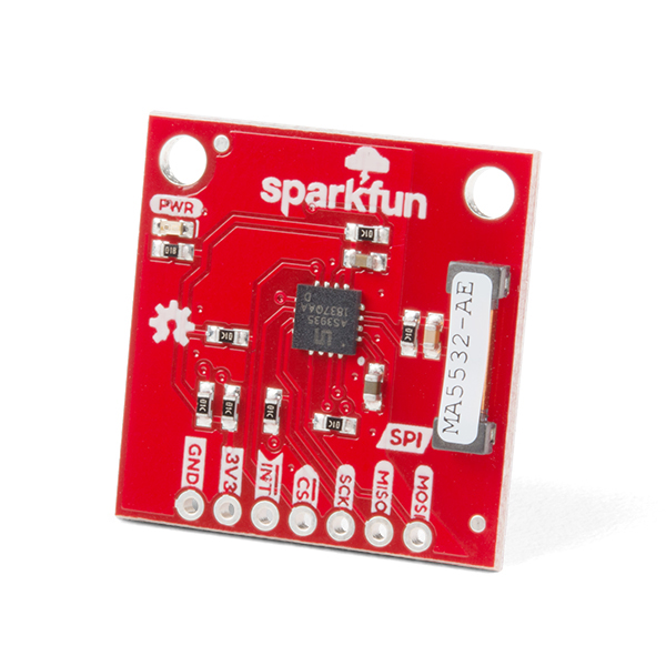
I am running a SparkFun Lightning Detector - AS393527 SEN-15441, connected to a SparkFun Thing Plus - ESP32 WROOM (USB-C) WRL-20168. All activity on the SPI bus (VSPI or HSPI) MOSI pin causes the AS3935 to generate disturbers and/or false lighting strikes - which exactly coincide with the activity on the SPI MOSI pin.
How can I overcome the SPI-caused interference? Note that I have tried methodically adjusting all parameters on the AS3935. Makes no difference.
Your workbench
- What development board or microcontroller are you using? SparkFun Thing Plus - ESP32 WROOM (USB-C) WRL-20168
- What version of hardware or breakout board are you using? Unknown
- How is the breakout board wired to your microcontroller? Breadboard & short jumpers
- How is everything being powered? Either 5VDC regulated supply or 1 cell LiPo (makes no difference)
- Are there any additional details that may help us help you? Please see below...
I am running a SparkFun Lightning Detector - AS393527 SEN-15441, connected to a SparkFun Thing Plus - ESP32 WROOM (USB-C) WRL-20168. The SPI bus (VSPI) is connected to and successfully talking with the AS3935 board. VSPI is also connected to and talking with the ESP32 on-board SD card (so I can datalog lightning strikes). I set up WiFi to set the time (NTP). Data is logged with Unix time stamps. I also connected the VSPI bus to a small TFT display. All features work as intended, except that I have proven (through process of elimination) that whenever the ESP32 sends data out the VSPI MOSI pin for the SD-Card or the TFT display it results in many disturbers and/or false lighting strikes. If I remove the SD-card and TFT code I get zero distrubers or false strikes. I changed VSPI bus speed in case it was a harmonic sending noise up the line or via RFI. I tried moving the TFT onto the HSPI bus but it made no difference. I attempted to move the AS3935 onto the HSPI bus (so does not share with SD card SPI) but could find find in the SparkFun_AS3935_Lightning_Detector_Arduino_Library how to redesignate SPI Pins.
Steps to reproduce
When any activity occurs on the ESP32 SPI bus pins, the AS3935 reliably gives false disturbers and/or false lightning strikes at the exact time there is activity on the SPI MOSI pin.
Expected behavior
The AS3935 should not give false distrubers or strikes, given that it is being operated away from common sources of RFI
Actual behavior
The AS3935 gives false disturbers and/or false lightning strikes rendering it useless
Full code can be found on https://forum.sparkfun.com/viewtopic.php?f=74&t=61502&p=249026#p249026
(Issue #248948). The code is almost 1000 lines so too long to paste here - but I do not think the coding will change the SPI RFI problem? Header information below...
// Nick Milton
String VersionNo = "46a";
String VersionDate = "28/04/2024";
// Version 28 is 1st version close to production ready
// Version 30 notifies user if ESP32 goes into WiFi AP rather than STA mode
// Version 31 - housekeeping on timers
// Version 37 added fn UpdateAllTimes() and call every 1 second (rather than only when AS3935 has an event)
// Version 41 testing live input from webpage to change AS3935 settings live . See https://randomnerdtutorials.com/esp32-esp8266-input-data-html-form/
// Version 41a the code added in 40 WORKS. Use 40 as the starting point and build itterations as letters until I get it integrated into my project
// V41b - adding 7 parameters for webupdate > modify A3935 settings after boot
// V41c - add IP address to startup screen. This version I have got working an ESP32 webpage to update AS3935 parameters remotely (but does not retain to NV memory or SD card file)
// V42 - play with alternative approach that uses physical buttons/switches NOT WiFi to adjust settings - so I can shut down WiFi after successful NTP time sync (adding state machine to see if this helpd do this)
// V43 - simplify ie get rid of live input from webpage. Set up simple input from local buttons. Aim - no WiFi once NTP timesync acchieved
// V43 - rebuild & simplify ie get rid of live parameter input from webpage. Set up simple input from local buttons to adjusr AS3935 params. Disable WiFi once NTP timesync acchieved to see if decreases false alerts
// Notes - when I put a 1 metre extension cable onto the AS3935 board it stopped the SPI working for SD Card and for the LCD screen - but the AS3935 SPI kept working. I think the wire is too long to work properly on shared SPPI bus
// Results - 1m cable does not decrease false alerts but does bugger SPI bus. Consdier no-WiFi version on the ESP32 and add an RTC?
// When I load a version of this code with no WiFi or LCD it seems to have far fewer false alarms even though I disabled WiFi (or did I?) in this version once clock is set
// V43b reinstated normal WiFi & NTP code so does not stop it running, but in this version DISABLED all LCD code in case it is this causing RFI.
// Result - get almost no false alerts or distrubers! So something to do with LCD SEEMS to be the culprit! Unplugging LCD from 3V3 pin does not make false alerts go away when running V44 of the code (which has LCD enabled)
// V44 WiFi enabled (cuts off after NTP sync success), LCD enabled, SD card enabled. Suffers huge number of false alerts
// V45 Move the LCD onto the second SPI ESP32 bus in case having AS3935, SD Card & LCD all on same bus is causing the false alerts
// RESULT - NO DIFFERENCE. STILL GET CTS distrubers and ALERTS - so it seems that the LCD code is cauing grief
// Finding 1 - if LCD code is removed then I get no false alerts even if LCD still connected & WiFI and SD card up and running
// Finding 2 - if LCD code remains in place and LCD power connected OR disconnected I still get false alerts
// Finding 3 - R45 code. If LCD is moved to it's own SPI bus then (with LCD code still in place and LCD connected or with all LCD wiring completely removed from the ESP32) I STILL GET many false alerts
// ***Fluke Finding - Running R45 code I noticed the EDP32 RGB LED (which I told to flash blue when AS3935 interrupts) flashes at exactly the SAME time as GPIO13 (on-board LED) which just happends to be the SPI bus#2 MOSI output.
// In other words whenever the ESP32 sends data down the MOSI line to the LCD (whether LCD connected or not) it causes huge number of false distrubers & strikes!
// SUMMARY - the LCD code generates MOSI data for the LCD which somehow is causing the false alerts even if on it's own SPI bus. Is this perhaps a harmonic of the AS3935 Rx? SPI_FREQUENCY was set to 40,000,000 for the LCD. If I set to 1,000,000 still get FTI
// FINDING 4 - Seems I need to either find a new TFT library (unliley will change anything) or a new non-graphic display (perhaps I2C LCD) which just sends the characters down the line not high-speed data
// V46 Base on V45, with
// (1) all TFT LCD libraries/code/calls commented out (to be replaced by LCD I2C display in time).
// (2) LiPo code added back in
// (3) SD card code retained
// (4) WiFi and NTP sync code retained and NOT stopped after 1st successful NTP time sync
// (5) Added RBG flashes to show when SD card write occurs
// (6) Added ORANGE to RGB status LED
// (7) Added 13 second log events to see if the SD card activity (on SPI) causes false triggers. IT DOES! Try putting the AS3935 onto the HSPI SPI bus so does not share with the SD card. See line 537
// ***New Finding - now that the TFT display and code are gone I can see that whenever the ESP32 accesses the SDCard over SPI bus it triggers disturbers & some false lignting events
//V46a disable all SD card writes (comment out the contents of the datalog fn) to see if get nil false alerts or disturbers
// Result - works perfectly ie no disturbers or noise or false alerts. So the ESP32 SPI bus seems to send noise up the line or impose leaky RFI all over the AS3935.
/*
Description_______________
~ SparkFun_AS3935 lightning detector + SparkFun ESP32 Thing Plus C + 1.69inch LCD Module.
~ Based in part on code by Elias Santistevan SparkFun Electronics July 2019 & code examples in the libraries below
~ need to tidy up whole progam now and to add a state machine to handle loss of Wifi or NTP sync Add h/w interrupts & routines to check WiFi and NTP still connected/working
Key features
~ Franklin AS3935 board talks to ESP32 over SPI
~ ESP32 onboard RGB LED in use as a basic status indicator
~ ESP32 onboard SD card used to log event data + timestamps as Epoch. Each time ESP32 restarts creates new file names 'datalog_' + UnixTime + '.txt'
~ WiFi manager AP and STA mode support - WiFiManager sets up STA mode via temp AP mode
~if I restart ESP32 after flush (and I do not enter new credentials, or if I enter invalid credentials for my WiFi network) then on reboot it will enter AP mode.
~if there is no WiFi network to join I want it to then allow AP mode to timeout and have it continue to boot ESP32 with no network connected - rather than have cts cycle to AP mode
~ NTP time sync then WiFi shutoff (to prevent RFI)
~ Monitoring of MAX17048 LiPo fuel gauge stats
Wiring
SPI for reference..
SPI Bus 1 (VSPI) and 2 (HSPI)
SPI MOSI MISO SCLK CS
VSPI GPIO 23 GPIO 19 GPIO 18 GPIO 5
HSPI GPIO 13 GPIO 12 GPIO 14 GPIO 15
SPI bus 1 (VSPI) used for SD card & AS3935
Sparkfun AS3935 pins USE Sparkfun ESP32 Thing Plus C pins
MOSI SPI ESP>Lignthing GPIO23 (MOSI aka VSPID aka PICO)
MISO SPI ESP<Lignthing GPIO19 (MISO aka VSPIQ aka POCI)
SCK SPI Master clock > Lignthing GPIO18 (SCK)
CS SPI Master > select slave GPIO25
INTERUPT Inst DO Lightning > ESP32 GPIO32
3V3 Power from ESP23 > Lightning 3V3
GND Power and signal ground GND
SPI bus 1 (HVSPI) if used for AS3935. Not sure if it can be. SEE BELOW OPTION
1.69' LCD Display wiring (ST7789V2, Display IPS, 240 X 280)
Display USE WIRE COLOUR ESP32 REMARK
VCC 3.3V purple 3.3V Supply to the LCD
GND GND white GND Common
DIN MOSI green GPIO23 Shared with AS3935 & also with the SD card. Should I use the 2nd SPI bus instead? How to define?
MISO GPIO19* Not used by LCD but is set by SPI bus
CLK SCLK orange GPIO18 SPI clock
CS yellow GPIO15 Slave select. Set low to select
DC blue GPIO33 Data/command control pin. Set 0 to write command. Set 1 to write data
RST brown GPIO27 pull low to reset when powered LCD on
BL grey GPIO26 LCD backlight control.
SPI bus 2 (HSPI) used if used for LCD * AS3935
1.69' LCD Display wiring (ST7789V2, Display IPS, 240 X 280)
Display USE WIRE COLOUR ESP32 REMARK
VCC 3.3V purple 3.3V Supply to the LCD
GND GND white GND Common
DIN MOSI green GPIO13 use the 2nd SPI bus instead
MISO GPIO12* Not used by LCD but is set by SPI bus
CLK SCLK orange GPIO14 SPI clock
CS yellow GPIO15 Slave select. Set low to select
DC blue GPIO33 Data/command control pin. Set 0 to write command. Set 1 to write data
RST brown GPIO27 pull low to reset when powered LCD on
BL grey GPIO26 LCD backlight control.
// MyDisplay text arrangement
Row Use
1 LIGHTNING
2 not used
3 Time in red of strike
4 Range in red of strike
5 Time of day in white
6 Disturber in blue or Noise in yellow
7 Time of disturber (in blue) or noise (in yellow)
Text 2 font spaced 20 pixes apart (y). Get around N characters/line
Text 4 font spaced 30 pixes apart (y). Get around N characters/line
ESP32 ob-board LED
~ PowerLED red
~ GPIO13 LED blue - shows WiFiManager reset button state
~ LiPo charge LED yellow
~ WS2812 RGB LED for which colours have following meanings:
GREEN - AS3935 connected
RED - lightning detected - flash during operation
YELLOW - radio noise
BLUE - radio distruber
WHITE - SD card file create or file append
PURPLE - NTP time sync success
ORANGE - NTP time sync fail
Buttons & switches:
GPIO13 MOM push button > reset WiFiMAnager STA credentails
GPIO16 BUTTON - LONG (1 Sec) push toggle from RUN <> CONFIG mode. SHORT push SCROLL through all config items in a loop
GPIO21 & GPIO22 UP/DOWN SWITCH - press up to increase menu item value, or down to decrease value