Coder Social home page Coder Social logo

micromod_esp32_processor's Introduction

SparkFun MicroMod ESP32 Processor Board

SparkFun MicroMod ESP32 Processor Board

SparkFun MicroMod ESP32 Processor Board (16781)

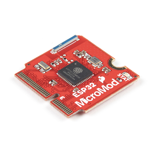
The MicroMod ESP32 Processor Board combines Espressif's ESP32 with our M.2 connector interface to bring a power-packed processor board into our MicroMod ecosystem.

The ESP32 includes a laundry list of functionality, including the dual-core Tensilica LX6 microprocessor, 240MHz clock frequency, 520kB internal SRAM, integrated WiFi transceiver, and hardware accelerated encryption (AES, SHA2, ECC, RSA-4096). With this MicroMod processor board, you have access to 8 general use IO pins, dedicated analog, digital, and PWM pins, as well as all the fan favorites - SPI, I2C, UART, and SDIO. Add to that 16MB flash storage and sleep current of around 500ÂľA, and you've got a perfect storm of versatility.

Grab yourself a SparkFun MicroMod ESP32 Processor Board and a compatible carrier board and get to hacking!

Repository Contents

  • /Documentation - Data sheets, additional product information
  • /Hardware - Eagle design files (.brd, .sch)
  • /Production - Production panel files (.brd)

Documentation

  • Hookup Guide - Basic hookup guide for the SparkFun MicroMod ESP32 Processor Board.
  • Getting Started with MicroMod - A tutorial to help you get started with the MicroMod Ecosystem.
  • Designing with MicroMod - A tutorial to walk you through the specs of the MicroMod processor and carrier board as well as the basics of incorporating the MicroMod form factor into your own PCB designs.

License Information

This product is open source!

Please review the LICENSE.md file for license information.

If you have any questions or concerns on licensing, please contact technical support on our SparkFun forums.

Distributed as-is; no warranty is given.

  • Your friends at SparkFun.

micromod_esp32_processor's People

Contributors

arctictron avatar awende avatar bboyho avatar loricrotser avatar

Stargazers

 avatar  avatar  avatar  avatar  avatar

Watchers

 avatar  avatar  avatar  avatar  avatar  avatar

micromod_esp32_processor's Issues

Hardware revision request: Improve power efficiency

Hi folks,

Unfortunately, the ESP32 MicroMod Process cannot achieve low quiescent draw when in deep sleep. I figured I'd throw this up on GitHub just in case the ESP32 ever sees a hardware revision.

Quoting @cheem from the forums: https://forum.sparkfun.com/viewtopic.php?f=182&t=58183

Unfortunately the CP210X USB to serial chip on the ESP32 module is connected to the 3.3V rail and not bus powered from 5V. The suspend pin is not utilized either which could reduce the quiescent current but is rather useless since the chip only needs to be active with a USB connection. A few traces need to be cut along with some jumper wires added to remove the VREGIN pin from 3.3V and add to V_USB power. It was relatively straight forward to do with a microscope and some 32 AWG wire. The bus powered configuration is shown in the typical connection diagram on page 18 of the CP210X datasheet (https://www.silabs.com/documents/public ... 2102-9.pdf). Afterwards my deep sleep 3.3V current dropped from 3mA to under 10uA.

At the very least, the product page should remove the stated 500 uA hibernation draw.

Cheers,
Adam

ESP32 automatic reset into bootloader fails due to missing capacitor on RESET (EN) signal

Issue

I get an error message like the following when trying to program the MicroMod ESP32 Processor board with esptool.py using the automatic reset hardware built onto the board:

esptool.py v3.3
Serial port /dev/cu.usbserial-2130
Connecting......................................

A fatal error occurred: Failed to connect to Espressif device: Wrong boot mode detected (0x13)! The chip needs to be in download mode.
For troubleshooting steps visit: https://docs.espressif.com/projects/esptool/en/latest/troubleshooting.html

Solution

I think the board is missing a capacitor between the RESET# signal (connected to ESP32 CHIP_PU/EN) and GND. This capacitor is required for the automatic reset circuit to work reliably.

image

See https://docs.espressif.com/projects/esptool/en/latest/esp32/advanced-topics/boot-mode-selection.html#automatic-bootloader, specifically:

adding a capacitor between the EN pin and GND (in the 1uF-10uF range) is necessary for the reset circuitry to work reliably

Rework

Here's some photos of the rework I did to get things working in case somebody comes across this issue in the future.

image

image

After adding a 1 uF capacitor between the RESET# signal and GND, programming via esptool.py works correctly:

esptool.py v3.3
Serial port /dev/cu.usbserial-2130
Connecting....
Detecting chip type... Unsupported detection protocol, switching and trying again...
Connecting....
Detecting chip type... ESP32
Chip is ESP32-D0WDQ6-V3 (revision 3)
Features: WiFi, BT, Dual Core, 240MHz, VRef calibration in efuse, Coding Scheme None
Crystal is 40MHz
MAC: 24:6f:28:8f:5d:bc
Uploading stub...
Running stub...
Stub running...
Changing baud rate to 921600
Changed.
Configuring flash size...
Auto-detected Flash size: 16MB
Flash will be erased from 0x00001000 to 0x00007fff...
Flash will be erased from 0x00008000 to 0x00008fff...
Flash will be erased from 0x00010000 to 0x00033fff...
Flash params set to 0x0240
Wrote 32768 bytes at 0x00001000 in 0.5 seconds (531.7 kbit/s)...
Hash of data verified.
Wrote 16384 bytes at 0x00008000 in 0.2 seconds (582.0 kbit/s)...
Hash of data verified.
Wrote 147456 bytes at 0x00010000 in 2.0 seconds (595.1 kbit/s)...
Hash of data verified.

Leaving...
Hard resetting via RTS pin...

Bootstrap pins on MicroMod connector can cause incompatibilities

Hi there,

I'm one of the SPE design challenge participants, so I received a Single Pair Ethernet kit that includes this board. When I started to play with this kit, I realized that I couldn't flash the Esp32! This was my first time working with one, so I subsequently learned about the bootstrap pins, and then realized that GPIO12 on the Esp32 (broken out to PWM1 (pin 47?) on the MircoMod connector) was being pulled high by the SPE function board. See sparkfun/SparkFun_MicroMod_Single_Pair_Ethernet_Function_Board_ADIN1110#1.

Work Around

I was able to burn the efuses on the Esp32 with espefuse.py set_flash_voltage 3.3V to hard-code the MCU's internal flash to 3.3V.

Possible Solutions

While the work around seems to allow the boards to work together, it doesn't seem like the ideal solution, as it requires some specialized knowledge to get to that solution, and is an irreversible action. The only way I could see this being feasible is if Sparkfun did the fuse setting before shipping these boards to customers. The most robust solution, though maybe too limiting, is to remove the bootstrap pins from the MicroMod connector entirely. This would prevent any incompatibilities with future function boards.

Anyway, I would love to hear your thoughts on this! :) Thanks!

Recommend Projects

  • React photo React

    A declarative, efficient, and flexible JavaScript library for building user interfaces.

  • Vue.js photo Vue.js

    🖖 Vue.js is a progressive, incrementally-adoptable JavaScript framework for building UI on the web.

  • Typescript photo Typescript

    TypeScript is a superset of JavaScript that compiles to clean JavaScript output.

  • TensorFlow photo TensorFlow

    An Open Source Machine Learning Framework for Everyone

  • Django photo Django

    The Web framework for perfectionists with deadlines.

  • D3 photo D3

    Bring data to life with SVG, Canvas and HTML. 📊📈🎉

Recommend Topics

  • javascript

    JavaScript (JS) is a lightweight interpreted programming language with first-class functions.

  • web

    Some thing interesting about web. New door for the world.

  • server

    A server is a program made to process requests and deliver data to clients.

  • Machine learning

    Machine learning is a way of modeling and interpreting data that allows a piece of software to respond intelligently.

  • Game

    Some thing interesting about game, make everyone happy.

Recommend Org

  • Facebook photo Facebook

    We are working to build community through open source technology. NB: members must have two-factor auth.

  • Microsoft photo Microsoft

    Open source projects and samples from Microsoft.

  • Google photo Google

    Google ❤️ Open Source for everyone.

  • D3 photo D3

    Data-Driven Documents codes.