SPI TFT and XPT2046 touch screen controller driver for esp-idf.
esp-idf v4.4 or later.
This is because this version supports ESP32-C3.
git clone https://github.com/nopnop2002/esp-idf-ili9340
cd esp-idf-ili9340/
idf.py set-target {esp32/esp32s2/esp32s3/esp32c3}
idf.py menuconfig
idf.py flash
Note for ESP32S2
Pull Up of the RESET pin may be required. I inserted a 100 ohm resistor between Vcc and RESET.
Note for ESP32S3
Pull Up of the RESET pin may be required. I inserted a 100 ohm resistor between Vcc and RESET.
Note for ESP32C2
For some reason, there are development boards that cannot use GPIO06, GPIO08, GPIO09, GPIO19 for SPI clock pins.
According to the ESP32C3 specifications, these pins can also be used as SPI clocks.
I used a raw ESP-C3-13 to verify that these pins could be used as SPI clocks.
You have to set this config value with menuconfig.
- CONFIG_WIDTH
- CONFIG_HEIGHT
- CONFIG_OFFSETX
- CONFIG_OFFSETY
- CONFIG_MOSI_GPIO
- CONFIG_SCLK_GPIO
- CONFIG_CS_GPIO
- CONFIG_DC_GPIO
- CONFIG_RESET_GPIO
- CONFIG_BL_GPIO
GPIO of ESP32 cannot supply too much current.
TFT backlight becomes brighter when powered by an external power source.
TFT MISO is not use.

M5Stack
4.0" ST7796S 480x320
3.2" ILI9341 320x240
2.8" ILI9341 320x240
2.4" ILI9341 320x240
2.2" ILI9340 320x240
2.0" ILI9225 176x220
2.0" ILI9225G 176x220
1.8" ST7735 128x160
1.77" ST7735 128x160
1.44" ST7735 128x128
0.96" ST7735 80x160


BMP file

JPEG file(Cannot be displayed on ESP32S2)

PNG file


Left:4.0" Right:2.4"


Left:3.2" Right:2.4"

Left:2.8" Right:2.4"


Left:2.2" Right:2.4"


Left:2.0" Right:2.4"


Left:2.0" Right:2.4"


Left:1.8" Right:2.4"


Left:1.77" Right:1.8"


Left:1.44" Right:2.0"


GRAM Offset may be different

Left:1.44" Right:0.96"

The ESP-IDF component includes Tiny JPEG Decompressor.
The document of Tiny JPEG Decompressor is here.
This can reduce the image to 1/2 1/4 1/8.
The ESP-IDF component includes part of the miniz library, such as mz_crc32.
But it doesn't support all of the miniz.
The document of miniz library is here.
And I ported the pngle library from here.
This can reduce the image to any size.
You can add your original fonts.
The format of the font file is the FONTX format.
Your font file is put in font directory.
Your font file is uploaded to SPIFFS partition using meke flash.
Please refer this page about FONTX format.
There is a font file editor.
This can be done on Windows 10.
Developer page is here.

This library uses the following as default fonts:
- font/ILGH16XB.FNT // 8x16Dot Gothic
- font/ILGH24XB.FNT // 12x24Dot Gothic
- font/ILGH32XB.FNT // 16x32Dot Gothic
- font/ILMH16XB.FNT // 8x16Dot Mincyo
- font/ILMH24XB.FNT // 12x24Dot Mincyo
- font/ILMH32XB.FNT // 16x32Dot Mincyo
From 0x00 to 0x7f, the characters image of Alphanumeric are stored.
From 0x80 to 0xff, the characters image of Japanese are stored.
Changing this file will change the font.
step1)
download fontxedit.exe.
step2)
download BDF font file from Internet.
I downloaded from here.
fontxedit.exe can ONLY import Monospaced bitmap fonts file.
Monospaced bitmap fonts can also be downloaded here.
step3)
import the BDF font file into your fontxedit.exe.
this tool can convert from BDF to FONTX.

step4)
adjust font size.

step5)
check font pattern.

step6)
save as .fnt file from your fontedit.exe.

step7)
upload your font file to $HOME/esp-idf-ili9340/font directory.
step8)
add font to use
FontxFile fx32L[2];
InitFontx(fx32L,"/spiffs/LATIN32B.FNT",""); // 16x32Dot LATIN
Font file that From 0x00 to 0x7f, the characters image of Standard ASCII are stored.

Font file that From 0x80 to 0xff, the characters image of Japanese are stored.

Font file that From 0x80 to 0xff, the characters image of Latin are stored.


The ESP32 series has three SPI BUSs.
SPI1_HOST is used for communication with Flash memory.
You can use SPI2_HOST and SPI3_HOST freely.
When you use SDSPI(SD Card via SPI), SDSPI uses SPI2_HOST BUS.
When using this module at the same time as SDSPI or other SPI device using SPI2_HOST, it needs to be changed to SPI3_HOST.
When you don't use SDSPI, both SPI2_HOST and SPI3_HOST will work.
Previously it was called HSPI_HOST / VSPI_HOST, but now it is called SPI2_HOST / SPI3_HOST.
There is a TFT equipped with XPT2046.

A library of XPT2046 Touch Screen is included in this project.
Use the menu to enable XPT2046.

- Touch position accuacy
The coordinates read from XPT2046 are not stable.
The difference between the coordinates read last time and the coordinates read this time is determined, and if it is within this range, it is regarded as a valid coordinate.
Decreasing this value will make the position more accurate, but less responsive.
Increasing this value will make the position more inaccurate but more responsive.
There is a TFT equipped with HR2046.
XPT2046 and HR2046 are very similar. But HR2046 does not work properly.

| TFT | ESP32 | ESP32-S2 | ESP32-S3 | ESP32-C3 | ||
|---|---|---|---|---|---|---|
| VCC | -- | 3.3V | 3.3V | 3.3V | 3V3 | |
| GND | -- | GND | GND | GND | GND | |
| CS | -- | GPIO14 | GPIO34 | GPIO34 | GPIO9 | |
| RES | -- | GPIO33 | GPIO41 | GPIO41 | GPIO1 | (*1) |
| D/C | -- | GPIO27 | GPIO40 | GPIO40 | GPIO10 | (*1) |
| MOSI | -- | GPIO23 | GPIO35 | GPIO35 | GPIO19 | (*1) (*2) |
| SCK | -- | GPIO18 | GPIO36 | GPIO36 | GPIO18 | (*1) (*2) |
| LED | -- | 3.3V | 3.3V | 3.3V | 3.3V | (*1) (*3) |
| MISO | -- | N/C | N/C | N/C | N/C | |
| T_CLK | -- | GPIO18 | GPIO36 | GPIO36 | GPIO18 | (*1) (*2) |
| T_CS | -- | GPIO22 | GPIO38 | GPIO42 | GPIO5 | (*1) (*4) |
| T_DIN | -- | GPIO23 | GPIO35 | GPIO35 | GPIO19 | (*1) (*2) |
| T_OUT | -- | GPIO19 | GPIO37 | GPIO37 | GPIO3 | (*1) (*2) |
| T_IRQ | -- | GPIO21 | GPIO39 | GPIO45 | GPIO4 | (*1) (*4) |
(*1) You can change it to any gpio using menuconfig. But some gpio's are input only.
(*2) SPI is shared by TFT and XPT2046.
(*3) It can be controlled using gpio. However, GPIO of ESP32 cannot supply too much current. TFT backlight becomes brighter when powered by an external power source.
(*4) I found that there are limits to the GPIOs that can be used as touch panel controls.
You can check if XPT2046 works properly.

If you touch it at this time, the touched coordinates will be displayed.
If there is no touch for 10 seconds, it will end.

Move the touch-pen vertically and horizontally to check the X and Y coordinates.
What you get here is the physical coordinates.
See here about physical coordinates.

Keep touching the point.


If there is no touch for 10 seconds, it will end.

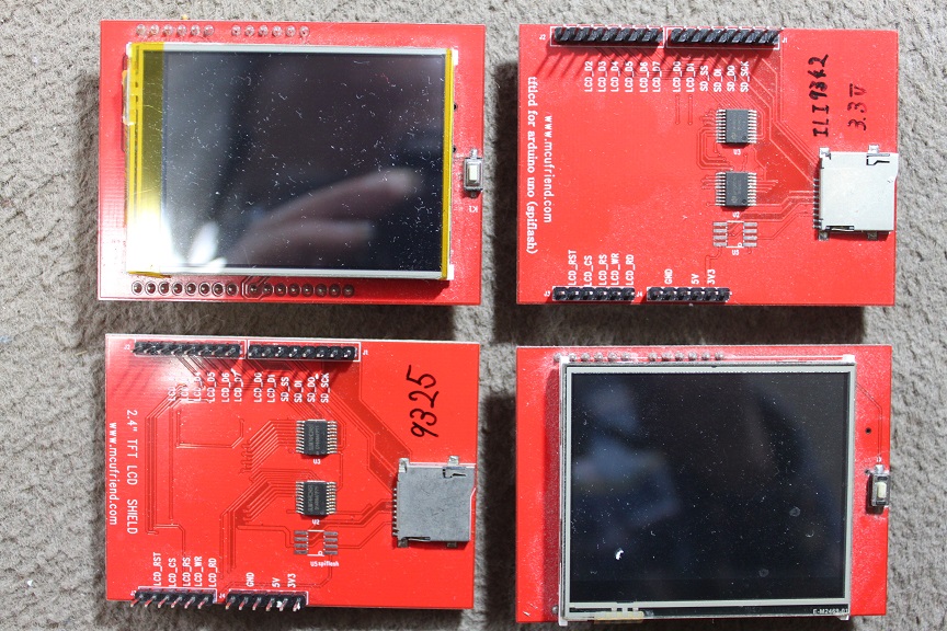
You can use TFT Shield like this: