An UPS (Uninterruptible Power Supply) made of my old (broken) UPS and Arduino.
The documentation consists of hardware and software part.
The hardware documentation consists of used parts and electrical schemes. It resides in "hw_doc" directory.
The software documentation consists of action diagrams. It resides in "sw_doc" directory.
Source code is included as well and can be found in "arduino_ups" directory.
Every aspect of this project is thoroughly explained in this documentation.
- Old UPS (or a box to put everything in)
- 12V 7Ah battery
- 12V power brick
- Arduino Uno
- LCD Keypad Shield
- Breadboard (using a smaller one)
- Wires
- Transistor (N MOSFET)
- Resistors: 20k, 10k, 2.2k
- Buzzer
- Power panel connectors
- Polymer fuses: one >=13V >=7A (main power), one >=13V >=1A (buzzer fuse :) )
- Drill
- Screwdriver

The power from the power brick goes into "Input 12V DC" jack. Then it leads to the polymer fuse. From there it goes to the bread board and Arduino Uno power jack. The LCD Keypad Shield is directly connected to the Arduino board. The LCD Keypad Shield is used for user interaction.
For voltage measuring I used voltage divider, which uses Ohm's law. R1 resistor is 20k, R2 is 10k
The calculation and the picture of the scheme for voltage measuring is shown below.
We need to calculate, what the maximum input voltage from the power source can be, before the Arduino blows on fire :) The closer it is to the nominal voltage of the power brick (in this case 12V), the more accurate voltage readings we will get, but the less headroom we will have, when the voltage starts fluctuating (which is rather unlikly but possible).
Vout = ouput voltage (to the Arduino input pin) Vin = input voltage (from the power source) R1, R2 = resistance values of R1 and R2
Vout can be at most 5V beacuse we can provide to the Arduino input pins AT MOST 5V! Otherwise we will fry the Arduino.
Equations...
Vout = (Vin * R2) / (R1 + R2)
Vout * (R1 + R2) = Vin * R2
(Vout * (R1 + R2)) / R2 = Vin
Now we can replace the variables with the values.
Vout = 5V
R1 = 20k = 20000
R2 = 10k = 10000
(Vout * (R1 + R2)) / R2 = Vin
(5 * (20000 + 10000)) / 10000 = Vin
Vin = 15V => 15V can be the maximum input volate to the voltage divider from the power brick.
You don't have to do the math by hand. Instead, use a calculator for voltage divider to do the job for you. You can customize there everything you need.

A N-channel MOSFET was needed to drive a buzzer (piezo speaker), which was rated for 12V. Pin #3 on Arduino was outputting PWM signal to the MOSFET's gate through the 2.2k resistor. The frequency of the PWM signal was transfered to the speaker, which then produced tone at that frequency.
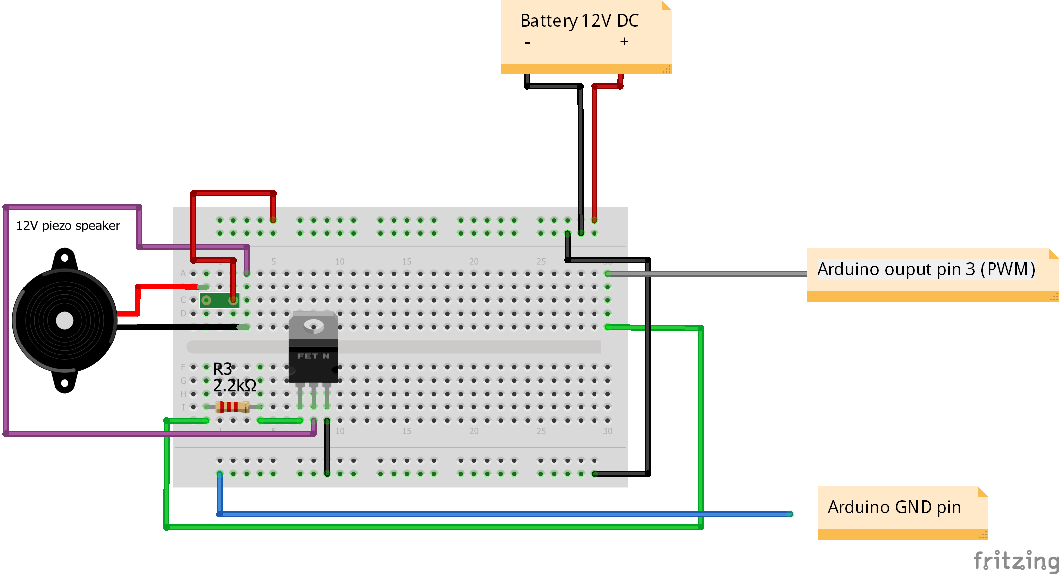
The physical scheme (Arduino_UPS.fzz, Buzzer.fzz and Voltage_divider.fzz) has been made with the help of Fritzing.
Using the computation mentioned in the hardware documentation, the maximum voltage that we can measure is 15 Volts. However the Arduino analog input pins can handle only 5 Volts which is why we put a voltage divider in between the battery and Arduino. The voltage that the voltage divider ouputs to the Arduino is less than 5V. In the program, the voltage is reversly transformed into the original voltage of the battery. The calculated voltage of the battery is then send to the LCD Keypad Shield to be outputted on the display.
The buzzer provides an acoustic feedback about the voltage level of the battery. If it's too high or low (according to measuring and ATX2.2 standard), the buzzer starts beeping (different sounds for too low and too high levels). When everything is all right, the buzzer is silent. Below we can see the activity diagram (state chart) for the buzzer. The buzzer can exist in three (transition) states:
| State | Description | Explanation |
|---|---|---|
| State 1 | Not beeping -> Start beeping | Starts beeping |
| State 2 | Started beeping -> Keep beeping | Continues beeping certain amount of time |
| State 3 | Enough beeping -> Stop beeping | After the beeping time is over, the buzzer is silent for certain amount of time. Then the buzzer can start beeping again. |
Table created with the help of tablesgenerator.com.

This activity diagram produces one beep of certain length and then the buzzer becomes silent for a certain amount of time.
I was considering to split the user interaction on hardware and software part, but instead I decided to put everything about it here.
The user can interact with the UPS using the buttons. The function of each button is explained below. After pressing a button, a responsible action is taken which is defined in function "execBtnAction".
The DEBUG buttons are inactive! Their function is to test the voltage limits. When the voltage limits are crossed, the user gets feedback from the buzzer.
Button 1 - DEBUG - Voltage up
Button 2 - Mute/Unmute the buzzer
Button 3 - Brightness up
Button 4 - Brightness down
Button 5 - DEBUG - Voltage down
Button 6 - Reset (can't be changed, it's hardwired to Arduino)

The program does exactly what is depicted in the activity diagram below. Most of the variables are declared and initialized in the "setup" function. The "loop" function takes care of the continuous program run. In addition to that, debugging printouts to serial console are distributed all over the code to monitor program's behavior on demand.

The activity diagram has been made with the use of draw.io.
The entire code doesn't contain any "delay" function call, so that the program is very responsive, fast and stable. The avoidance of using the "delay" function allows to use buttons for user interaction, which would be otherwise problematic and cumbersome.
The source code is in the file arduino_ups.ino and can be found in directory "arduino_upc".
How to Use a Buzzer (or Piezo Speaker) - Arduino Tutorial
http://www.instructables.com/id/How-to-use-a-Buzzer-Arduino-Tutorial/?ALLSTEPS
Piezzo Speaker - DBX12
http://www.db.com.hk/dbtronix/site/products_detail.php?pID=152
IRFZ 24N :: Power MOSFET N-channel TO-220AB 55 V 17 A
https://www.reichelt.de/Transistors-IRFU-IRFZ-/IRFZ-24N/3/index.html?ACTION=3&GROUPID=2894&ARTICLE=41737&OFFSET=16&SID=12VLelR38AAAIAABdkn9cb2bfeae5b6b044ddd7148786155b03ea&LANGUAGE=EN
IRFZ24NPBF - Documentation for the tranzistor (the closest i could find)
http://cdn-reichelt.de/documents/datenblatt/A100/IRFZ24N_IR.pdf
IRF740 - Documentation (supplemental documentation to the one mentioned above)
http://www.vishay.com/docs/91054/91054.pdf
Scheme - Controlling high voltage motor with tranzistor and Arduino
http://bildr.org/2011/03/high-power-control-with-arduino-and-tip120/
http://bildr.org/blog/wp-content/uploads/2011/03/tip120-motor.png
Fritzing - The scheme-making tool
http://fritzing.org/learning/
Fritzing - LCD Keypad Shield
https://github.com/RafaGS/Fritzing/blob/master/LCD%20Keypad%20Shield.fzpz
Fritzing - tutorial
https://www.youtube.com/watch?v=M4CvUSkP9hw&t=3s
Arduino Uno pinout
https://micro-manager.org/wiki/Arduino
picoPSU-120 datasheet
http://www.mini-box.com/s.nl/it.A/id.417/.f
http://resources.mini-box.com/online/PWR-PICOPSU-120/PWR-PICOPSU-120-manual-engl.pdf
ATX v2.2 voltage tolerances
https://www.lifewire.com/power-supply-voltage-tolerances-2624583
Arduino - Blink without delay (huge efficiency improvement)
https://www.arduino.cc/en/Tutorial/BlinkWithoutDelay
const vs #define
http://forum.arduino.cc/index.php?topic=44023.0
LCD Keypad Shield demo code
https://www.dfrobot.com/wiki/index.php/Arduino_LCD_KeyPad_Shield_(SKU:_DFR0009)
LCD Keypad Shield - display brightness control
http://forum.arduino.cc/index.php?topic=97817.0
Tips and tricks for AVR controllers
http://www.nongnu.org/avr-libc/user-manual/FAQ.html
Variable types and modifiers explanation
https://stackoverflow.com/questions/3684760/where-are-the-local-global-static-auto-register-extern-const-volatile-var
