Coder Social home page Coder Social logo

nasa-jpl / open-source-rover Goto Github PK

View Code? Open in Web Editor NEW
8.3K 458.0 1.3K 2.84 GB

A build-it-yourself, 6-wheel rover based on the rovers on Mars!

Home Page: https://open-source-rover.readthedocs.io

License: Apache License 2.0

AMPL 9.39% Prolog 88.74% HTML 1.22% Python 0.53% Batchfile 0.06% Shell 0.06%
mars-rover mars robotics robot diy hardware open-source

open-source-rover's Introduction

JPL Open Source Rover Project

NOTE: For the previous major version of the OSR, please see v3.1.0.

The JPL Open Source Rover is an open source, build it yourself, scaled down version of the 6 wheel rover design that JPL uses to explore the surface of Mars. The Open Source Rover is designed entirely out of consumer off the shelf (COTS) parts. This project is intended to be a teaching and learning experience for those who want to get involved in mechanical engineering, software, electronics, robotics but is also an excellent research platform for rugged terrain. No prior skills or knowledge is required.

Youtube video of OSR2 in action

A gallery of some community builds including previous versions of the rover can be found here.

About the OSR

Motivation

JPL is always looking to inspire the next generation of scientists, engineers, and roboticists to help us explore and learn about our solar system (and beyond!). We release the plans for this rover as a way to try and give budding enthusiasts a fun robotics project that will help teach them and get them involved in robotics sooner and at a lower cost.

At a glance

The OSR has been around since 2017 and has undergone many iterations. It is a premium and robust robot with a unique look, high customizability, and powerful abilities. The hardware and electronics were designed with expansions like a head display and robot arm in mind.

spec value
top speed ~1.6m/s (~slow running, subject to motor selection
nb motors 10
structural material aluminum
total cost ~$1600 (about the cost of a TurtleBot 3 Waffle)

The OSR mostly uses parts from GoBilda for the mechanical assembly. For GoBilda's (international) shipping options, see here.

Other open-source, cheaper alternatives exist but are slower, less strong, and are more fragile. See Additional Projects.

Features

This rover is designed to function similarly to the 6 wheel rover designs on Mars and employs a few of the major driving mechanics that the mars rovers use to traverse rocky surfaces:

  • Rocker-Bogie: The Rocker-Bogie suspension system allows all 6 wheels to continually be in contact with the ground while climbing over obstacles
  • Differential Pivot: Allows weight to be mechanically offloaded from one side of the rover to the other while climbing
  • 6-Wheel Ackerman Steering: Driving and steering/turning mechanism that governs where the wheels point and how fast each of them will move.

A Raspberry Pi acts as the "brain" of this rover for its versatility, accessibility, simplicity, and ability to add and upgrade your own modifications. Any method with which you can communicate with a Raspberry Pi (bluetooth, WiFi, USB devices, etc) can be interfaced into the control system of the robot.

For a 7.2Ah battery and with some driving on rough terrain, expect to get at least 3 hours of drive time. Below chart was recorded while driving on rocky terrain and plots voltage, current draw, and commanded velocity over time. When the voltage drops below 13-14V, the rover will power down. You can increase drive time by getting a bigger battery and/or by having the rover carry a second battery that can be swapped out.

WARNING: Be careful to not discharge a LiPo battery too far as that drastically lowers the lifetime of your battery and can potentially make it hard or impossible to recharge.

power usage chart

Join a community of hundreds of builders

Considering building one yourself? The best way to ask questions, reach maintainers, learn about modifications, and join the community of Open Source Rover builders is to join our Slack group:

Note: JPL and Caltech have no official affiliation with this forum; it is run by individuals of the general public. On these you can ask questions if you need help or clarification on any aspects of the project. Additionally, you can post and promote any modifications or addons that you have created on this project. We highly encourage additions and modifications to be posted so that this project and community can grow.

Maintenance Status

As an open-source hardware project, the rover is continuously improving. Please check issues, pull requests, and the Slack forum to see if any big changes are expected soon. The OSR project is proud to be Open-Source Hardware certified!

OSHW certification US002551

Online 3D Model

You can view a 3D model of the latest version of the rover in your browser at OnShape.

Skills Necessary

This project has elements in mechanical assembly/fabrication, uses a host of electrical components, and has software that will run it all. In order to complete this project, you will need to have some experience in the following:

  • Fabrication/Machining: All parts are Consumer Off-The-Shelf (COTS) parts and no metal machining should be required to complete the 'base' version of the rover. However for any optional expansions, it may be useful to have access to the following skills/tools:
    • Metal cutting using band saw/dremel
    • Drilling using drill press/hand drill
    • Filing and sanding for part cleanup
    • General Fabrication/Machining Safety
  • Electronics: This project uses components like motors, motor controllers, and batteries. While prior experience with the following skills is not required, having access to someone who can help will save a lot of time:
    • Soldering
    • Electrical debugging
    • Wiring
    • Electrical Safety
  • Software: The rover's brain is a Raspberry Pi. All code can be found in the osr-rover-code repository along with step-by-step instructions to set it up. Basic familiarity with Linux, ROS, Git, and Python will be helpful though.

Most of the above are skills that you can learn and pick up fairly quickly from watching videos and doing research on the internet, and throughout the project we try to give supplemental information on some of these as well. See the build documents for more information.

Tools Necessary

This project assumes you have some standard tools to help assemble the project. If you do not have any of the optional tools, we provide examples of online services that you can use to have the parts fabricated and sent to you.

Mandatory tools

  • Metric hex keys
  • Pliers
  • Wire Snips
  • Wire Strippers
  • Solder Iron
  • Solder
  • Digital Multimeter
  • Wire strippers, e.g. these

Optional Tools

  • 3D printer
  • Laser Cutter (for the body plates, online services available)
  • Benchtop Power Supply (to test without using battery)
  • Items for operating a Raspberry Pi (Keyboard, mouse, monitor, 5V micro USB power adapter)

Expected time commitment

In our experience, this project takes no less than 100 person-hours to build, and depending on the familiarity and skill level of those involved could be significantly more. Experienced builders may be able to build this project in this amount of time. However, this project is generally meant to be a teaching and learning tool. Throughout the documentation, we try to give supplemental information for those who might be new to this kind of project.

Getting Started

Rover Build Roadmap

  • Stage 1: Order parts. You'll want to get started on this ASAP!

  • Stage 2: Create the wiring. The cables connect the Printed Circuit Board (PCB) in the body to each motor and integrate into the rocker-bogie and corner assemblies so they need to be built first.

  • Stage 3: Make the electronics: Soldering the PCB and installing into the rover along with peripheral connections. We'll also use the wiring to test your PCBs.

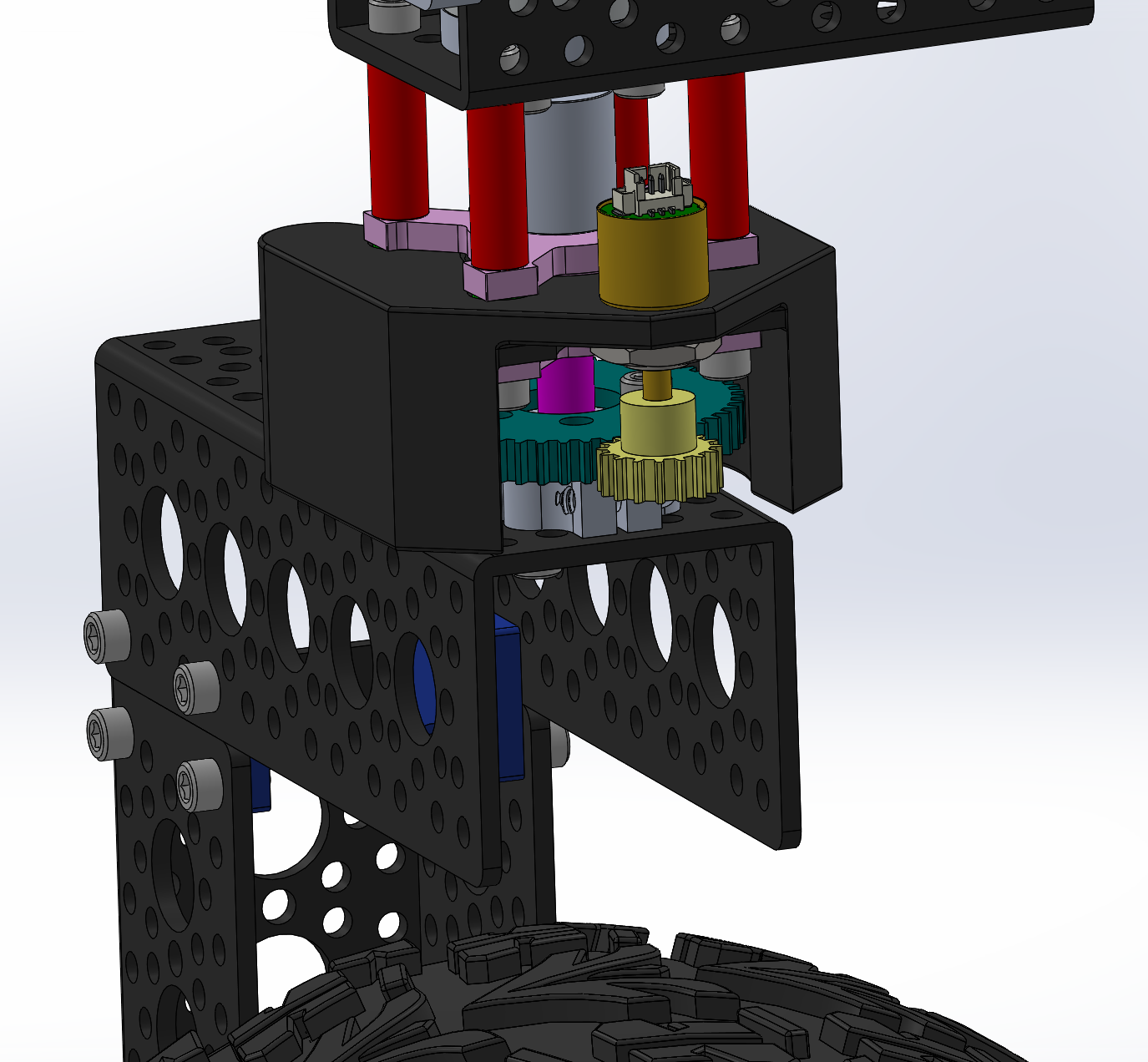
  • Stage 4: Make the mechanical assemblies: the body, the two rocker-bogies, the drive and corner motor assemblies. The instructions will guide you through how to do these step by step while integrating the cabling from Stage 2. You'll then attach them into something that will start to look like a rover!

  • Stage 5: Setting up and configuring the operating system rover code. The Rover Code repo's README files will walk you through all necessary steps for getting the rover software up and running on the Raspberry Pi. These steps can be completed at any point during the project, all the way up to when all the electronics and mechanical parts are completed and you are ready to start driving and controlling the robot.

  • What's next? Add your own upgrades! We chose Raspberry Pi as the brain of the project so that it should be easy to add, change, and upgrade to build exciting things on top of this already cool robot. Some upgrade ideas to get you brainstorming: sonar for collision detection, IMU for orientation / closed-loop driving / obstacle mapping, camera for object identification and tracking, sensor packages (temperature, pressure, humidity), solar panels, or even a robotic arm!

Ordering parts

Parts Lists

The Parts List Readme contains all the parts necessary to build the entirety of the robot as it is listed in our documentation.

Note that educational builders may apply for a 15% discount at GoBilda by filling out this form. Make sure you do this on time as processing times may vary.

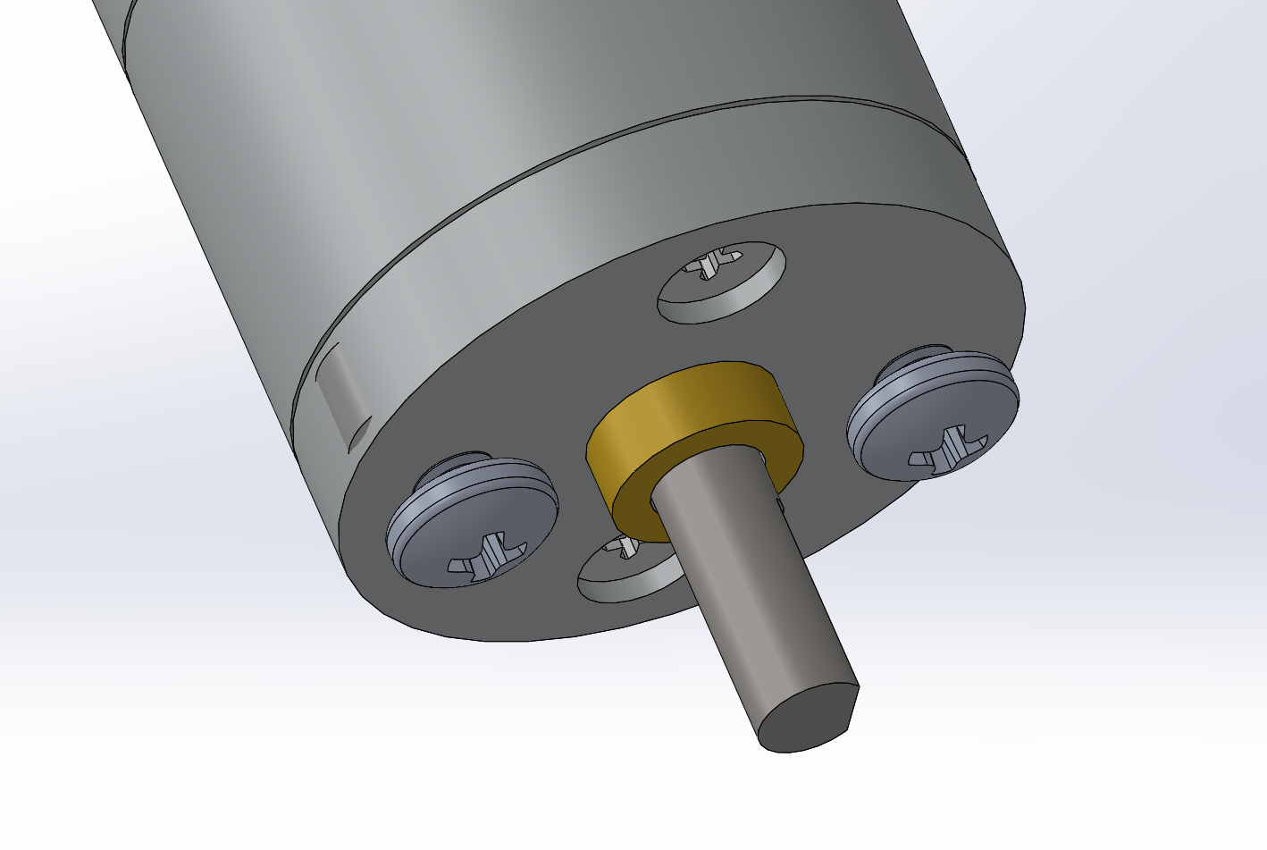
You can select higher RPM motors (to drive your rover faster) at the sacrifice of max stall torque. A selection of motors that would integrate easily with the rest of the suggested rover design can be found at GoBilda - 5203 series. The rover design and the software can accommodate different wheel sizes if you find wheels you like better.

Additional Projects

Take a look at these alternative Mars rover replicas:

Star History

Star History Chart

Disclaimer

Reference herein to any specific commercial product, process, or service by trade name, trademark, manufacturer, or otherwise, does not constitute or imply its endorsement by the United States Government or the Jet Propulsion Laboratory, California Institute of Technology. Government sponsorship acknowledged.

Licensed under Apache License 2.0.

OSR on the beach at night

open-source-rover's People

Contributors

0x48piraj avatar abust005 avatar achllle avatar angelnator1998 avatar apollokit avatar baehenrys avatar dcschooley avatar ejunkins avatar ericjunkins avatar github-actions[bot] avatar jarobey avatar jhphelan avatar josephgregg avatar joshsharpe avatar kasbah avatar kevincloutier avatar klauslex avatar kralmichal avatar mahran-sayed avatar mattbhenley avatar mikcox avatar rbrishabh avatar rcywongaa avatar sconaway avatar sethfischer avatar toebes avatar utnak avatar vharavu avatar xtream1101 avatar yambino avatar

Stargazers

 avatar  avatar  avatar  avatar  avatar  avatar  avatar  avatar  avatar  avatar  avatar  avatar  avatar  avatar  avatar  avatar  avatar  avatar  avatar  avatar  avatar  avatar  avatar  avatar  avatar  avatar  avatar  avatar  avatar  avatar  avatar  avatar  avatar  avatar  avatar  avatar  avatar  avatar  avatar  avatar  avatar  avatar  avatar  avatar  avatar  avatar  avatar  avatar  avatar  avatar  avatar  avatar  avatar  avatar  avatar  avatar  avatar  avatar  avatar  avatar  avatar  avatar  avatar  avatar  avatar  avatar  avatar  avatar  avatar  avatar  avatar  avatar  avatar  avatar  avatar  avatar  avatar  avatar  avatar  avatar  avatar  avatar  avatar  avatar  avatar  avatar  avatar  avatar  avatar  avatar  avatar  avatar  avatar  avatar  avatar  avatar  avatar  avatar  avatar  avatar

Watchers

 avatar  avatar  avatar  avatar  avatar  avatar  avatar  avatar  avatar  avatar  avatar  avatar  avatar  avatar  avatar  avatar  avatar  avatar  avatar  avatar  avatar  avatar  avatar  avatar  avatar  avatar  avatar  avatar  avatar  avatar  avatar  avatar  avatar  avatar  avatar  avatar  avatar  avatar  avatar  avatar  avatar  avatar  avatar  avatar  avatar  avatar  avatar  avatar  avatar  avatar  avatar  avatar  avatar  avatar  avatar  avatar  avatar  avatar  avatar  avatar  avatar  avatar  avatar  avatar  avatar  avatar  avatar  avatar  avatar  avatar  avatar  avatar  avatar  avatar  avatar  avatar  avatar  avatar  avatar  avatar  avatar  avatar  avatar  avatar  avatar  avatar  avatar  avatar  avatar  avatar  avatar  avatar  avatar  avatar  avatar  avatar  avatar  avatar  avatar  avatar

open-source-rover's Issues

Request for any documentation on software structure

I know how exactly much fun it is to write documentation, but it would be very helpful if the developers can add some text or diagrams describing the organization and structure of the rover software. In particular, I'd be interested in how the motor control layer works, as I might like to implement a different hardware controller for brushless DC motors. Thank you, developers, for this awesome and impressive project.

4-pin headers 0.1 not 0.05"

The specs call for common 0.1" headers on the PCBs. The master parts list, however, has a Digi-Key link to 0.05" headers. (as well as 40 pin 0.1" headers which I see no reference to x- perhaps to break into 4 pin units?) I searched the docs and found no reference to 0.05" anything. Error? If so, will need to swap out with Digi-Key.

Why is rover body tilted forward?

Why is rover body tilted forward? I don't see that the actual Mars rovers had a forward tilt. Is it just a happenstance of the choice/necessity of placement of the Differential Pivot and Rocker-Bogies? I find no mention of it in the build documents. I can reduce the tilt from ~14o to ~10o if I lengthen the turnbuckles from their minimum length to as long as I dare without them coming apart. There is no mention in the build as to whether or how to adjust them.

By the way, there is no mention of leaving any space between the main axle on the rocker-bogies and the ends of the differential pivot to avoid friction. I left a mm or two. I noticed there no lubricant washers next to the collar clamps along the main axle at the rocker-bogie arms & the body.

The last critical mechanical component, the 0.25" pillow bearing blocks are STILL on back-order in an apparent world-wide shortage! Though promised next week, we're going to try carbon-fiber 3D printing the blocks and inserting our own bearings. Will keep you posted how that goes.

Jim Phelan
Mars rover project lead
Houston Robotics

Drive Motor Clamp - Mechanical over-constraint

Problem

The attachment scheme for the drive motors leads to a mechanical over-constraint.

motor_clamp_1

Here we can see that the clamping force on the aluminum 25mm Diameter motor clamp will be over-constrained when bolting the clamp into the aluminum U-channel

motor_clamp_2

The red arrows show the force put on the piece from the clamping screw, and green arrows show force put on by bolting to the u-channel. These force are in direct opposition, and overtime lead to one of two things:

  • The motor loosens inside the clamp and is allowed to free spin, which will tangle and eventually break your wires
  • The clamp loosens inside the u-channel and the wheel assembly becomes loose to the rest of the robot chassis

Solution

The motor should mount on using the bolting pattern at the bottom of the motor, similar to the corner motor mounting scheme. This will alleviate this over constraint and allow all pieces to be tightened properly

motor_clamp_3

Get source files for the Build doc pdfs

Any way we can get access to the files that the build docs pdfs (well all if possible) were created from? This would make it easier to be able to edit and add modifications since right now the parts list and such are images in the pdf's.

Voltage Divider Board testing reversed

Houston Robotics, Mars Rover project, Electronics build team member Roberto Pensotti beautifully populated & soldered the three PCBs. While testing the Voltage Divider all checked out according to the directions up until step 9 at which point it failed. Repeating the test together during our weekly MeetUp failed again as did a fresh attempt at home the next morning. Instead of measuring just under 2V, it measured 0.2V or less. IC chip placement, resistor values & soldering technique all passed inspection.

Tracing the directions back from the pin number to the header designation to the schematic to the encoder function revealed that +5V signal voltage was being applied to the ENCn OUT pin and measured at the ENCn IN pin which seemed reversed. Reversing the directions, placing +5V at the ENCn IN pin & measuring at the ENCn OUT pin measured consistently about 1.6V. Test passed!

Jim Phelan, Mars Rover project lead, Houston Robotics

B10 screw incorrect

The Master Parts List lists B10 as a M2.5 x 4mm cap head screw.
The Electronics Board parts list shows 11mm.
For consistency (gasp!) it should be a button head screw to match the others on the board.
McMaster only has even sizes in M2.5 button head hex screws, so 10mm:
https://www.mcmaster.com/92095a460

Electronics Board: shortest RoboClaw needs 8 x #4 washers to make tight

The 5th RoboClaw motor controller on the Electronic board is supported by #4-40 1/4" stand-offs and 4-40 1/4" screws. 1/4" stand-off shared by 2 screws = 1/8" each. The Electronics Board is 1/8" acrylic allowing its screw to extend 1/8". The RoboClaw board is only 1/16" leaving a gap of 1/16" play when its screw meets its partner in the stand-off. A couple #4 washers does the trick and there's plenty left over. The purpose of the staggered elevation of the stand-offs is supposedly to allow room to access the USB port on the RoboClaw for testing and calibration. Seems this could have been accomplished as easily by rotation or translation of the RoboClaw but we won't know til wiring time what the reality of that situation is.
Jim Phelan, Mars Rover project lead, Houston Robotics

Git LFS storage is above quota

@vssystemluba, could you take a swing through the repo and compress the PDF files? As they are, they're ±40MB, and if compressed, they'd be ±2MB. The extra storage has consumed our Git LFS quota (which I didn't know about until I was notified). We'll look into how we can increase our available Git LFS storage space for our org, but until then, compressing the large PDFs will help. Happy to do that in a pull request. I simply use macOS Preview, and Save As using the Reduce File Size Quartz Filter.

Inconsistency in 'Electrical Parts List.xlsx'

  • Resistors 10K (row 11):
    Expected Resistor based on the name: 10 kOhms
    Resistor refered to in the Link column: 21 kOhms (digikey.com product page)
    Resistor found based on Model/Config column: 'CF14JT200KCT-ND' 200kOhms (digikey.com search)

  • Resistors 22K (row 12):
    Expected Resistor based on the name: 22 kOhms
    Resistor refered to in the Link column: 20 kOhms (digikey.com product page)
    Resistor found based on Model/Config column: '301KXBK-ND' 301 kOhms (digikey.com search)

Corrupted .stl files

I've seen reports on the forum that the .stl files don't load properly when users run git clone or download a .zip of the entire repository. People are reporting that the correct .stl files can be accessed by downloading the files individually.

See the thread on the forum for more details.

repeated vertical scale

"Maximum 90 deg vertical scale = 12 [in]"

Stair climbing would be "repeated 7 3/4 inches vertical / 10 inches horizontal", is that achievable without modification?

.dxf files for Electronics Board and Back body plate corrupted?

Previously downloaded & laser cut successfully both pieces. Recently noted post from member unable to download. Tried myself - able to download both files, but got "unrecoverable error" in CorelDraw and "failed to insert dxf" in Fusion360. Perhaps the file got corrupted?
Jim Phelan, Mars Rover project lead, Houston Robotics

Helpful jig for drilling clamping hub mounting holes in Traxx wheels

When the Houston Robotics Mars Rover team began to address the drilling of the mounting holes in the Traxxas wheels, we pondered how we might more accurately accomplish this. Initially we considered a vertical lathed spindle 12mm at the bottom to fit the wheel and 4mm at the top to fit the hub. Rotational orientation would still be by hand and there was concern that using the hub itself as a guide may damage the threads. We consulted the Houston Community College Stafford manufacturing campus Fab Lab supervisor Roland Fields. He suggested a more modern high tech approach of creating a 3D printed jig to fit the wheel hub to include appropriately spaced holes to guide pilot hole drilling. He directed us to lab assistant Frederic Lemme who whipped up a prototype on SolidWorks. After tweaking for fit, a further modification adding a hex nut shape to fit into the wheel ensured fixed alignment of the pilot hole guides to the target area. Houston Robotics' Omar Gomez and son accomplished the final drilling. The screws to attach the wheel to the hub seemed excessively long, but that's an issue for further along the build. ATTACHED is a drawing of the wheel adapter and zip file of the .SLDPRT and .STL files. Copyright 2018 Houston Robotics, free to use with acknowledgement.
wheel adapter v1

Jim Phelan, Mars Rover project lead, Houston Robotics
wheel_adapter3.zip

Coffee capabilities?

@vssystemluba Can this rover make enough coffee for 11 people co-located in a trailer? Specifically asking if it can operate the Technivorm Moccamaster. Going to need help soon and wondering if this is worth the investment.

Github Enhancement Proposal

Hello Project Owner, can I make a logo design for this project? I am a open source contributor and I am willing to work with you.

Clamping Hub: Mechanical over-constraint

Problem

There is a mechanical over-constraint imposed by the 0.25 inch clamping hub used to attach the corner wheel assemblies to the corner steering assemblies.

clamping_hub_1

This over-constraint is caused by the opposition of the clamping action of the clamping hub around the 1/4 inch shaft, and the bolting force attaching it to the aluminum U-channel

clamping_hub_2

The force caused by the clamping hub is shown in red, and force from the bolting to the U-channel is shown in green. There is not enough tolerance in the clamping hub to both very tightly grip around shaft and bolt to the u-channel.

Solution

In order to solve this issue you need to find a way to de-couple the attachment of the hub from the clamping force on the 0.25 in shaft. This could be done in many different ways, a few potential solutions would be:

  • Find a way to split this piece up into multiple pieces that are not coupled rigidly in those directions
  • Find a way to increase the mechanical tolerance in the bolting so that these forces are not in opposition

Potential Parts QTY inconsistency

Really looking for confirmation: I have just started reviewing osr_Master_parts_list.xlsx to prepare for this project. I expect column C (Qty in project) is the number used in the overall project (the sum of the sub-assembly part lists). In some instances this number does not match column B (Qty to Buy). I would expect this if the # required represents a partial consumption of a bulk order (line #34: 72 screws needed that are sold in lots of 100 - Qty to Buy = 100; Qty in project =72). In some cases these numbers do not agree (in one case the, line 79, the Qty in project > Qty to Buy). Can some one clarify is this is a data error or is my understanding of the two columns incorrect? Thanks.
image

T2 spacer/standoff - should it be 3/16 instead of 3/8?

In the Rocker-Bogie Assembly the build parts list does not include T2 the 6-32 3/8" standoff that is mentioned in the build. Two are shown attaching an F Pattern Bracket to each side of the 2nd modified 3" U channel with two B3 6-32 x 1/2" screws. There is no mention of using a nut, but the 3D pdf shows the screws penetrating the F Pattern Bracket, standoffs, U channel, hex nuts and extending into the U channel. (Washers are neither mentioned nor shown.) Using a 1/2" screw as listed, the screw barely penetrates the F Pattern Bracket and the 3/8" spacer. Trying a 1/4" spacer the screw penetrates the F Pattern Bracket, spacer and U channel but not sufficiently for a nut to grab on, let alone penetrate the nut and beyond. Perhaps what was meant was a 3/16" standoff or spacer? That should allow the nut to attach but not be penetrated. A 3/8" or even 1/4" spacer seems to give more room than necessary between the F pattern bracket and the U channel. The 3D pdf suggests the space is tighter. Was a 3/16" spacer intended instead? And/or was a longer screw than 1/2" intended (5/8 or 3/4")?
Issue discovered by Derrick & Alfredo, Rocker-Bogie build team, Mars Rover project, Houston Robotics

Yet another nit-pick from
Jim Phelan, Mars Rover project lead, Houston Robotics ;-))

Shaft Coupler -

Problem

There is sometimes slippage in the attachment between the shaft coupler and the motor shaft

shaft_coupler

(this image shows socket head cap screws, which have been switched to button head screws for more clearance)

Even with the de-coupling of the two clamping forces across the coupler it still sometimes does not grab onto the motor shaft well enough to hold the entire torque seen on the corners.

Solution

In order to keep the JPL open source rover up and running I've simply epoxied the couplers to the motor shafts, however for a hobby level project where one might want to change or reuse the motors this wouldn't be ideal.

Instead a coupler that can appropriately grab onto the 4mm motor shaft would be idea. This could potentially include a redesign of the scheme of attaching the motor so that you can get increased length of motor shaft to attach to as well.

Electrical assembly instructions figure 30

In fig 30, it appears that motor 1 is attached to M2 A&B but uses encoder #1. And similarly for the other 3 corner motors. I would have expected motor 1 to be associated with M1 A&B and encoder 1. Is this a typo or intentional?

On the other hand, I am having problems associating encoder 1 with Motor 1, when Motor #1 is wired to M1A/B and encoder 1's sensor wire (from input pin 2 to output pin 14 of the voltage divider) is wired to pin 7 of roboclaw 4.

Also: the Encoder Signals Schematic rev B is inconsistent with figures 29 & 30 of the elec assy instrs and the PCB with respect to numbering of the header groups.

Incorrect link in part list

Item

4.5 Inch Channel	4	4	1	ServoCity	S4	585444	Structural	 $4.99 	 $19.96 	4.5" x 12" Aluminum Pattern Plate

Links to item 585004 instead of 585444

Logic Shifter board testing confusion - put DIR & OE to GND instead of GPIO

In testing the Logic Shifter Board section 4 and Figure 22 indicate that the DIR and OE pins must be LOW (0V or GND).

DIR (pin 1, upper left) can be seen to connect on the schematic (via pathway "11" and demonstrated by following the PCB trace and proven by continuity check with a voltmeter) to header pin P4-3.

OE (pin 19, second right) connects (via pathway "10") to header pin P1-2.
These pins are shown connected by grey and white jumpers to Raspbery Pi GPIO pins 10 and 12.

However, unless there is a script running on the Pi to cause these pins to go LOW, they will "float" and be neither HIGH nor LOW preventing the chip from functioning properly. There is no mention of running a script on the pi for this test. Instead, we connected them to two of many spare GND pins on the RPi such as physical pins 9 and 14 to force them LOW.

+5V (P1-1) red wire to RPi +5V (pin 2). Check.

GND (P4-4) black wire to RPi GND (pin 6). Check.

During testing at each step the +3.3V purple wire to RPi +3.3V (pin 1) needs to march down the logic shifter headers P1-3 through P4-2. At each step confirm the +3.3V on the corresponding Bx pin on the right side of the shifter (according to the schematic) and look for the +5V on its partner Ax on the left side one pin up.

Thanks to Roberto Pensotti, Electronics build & testing team, Mars Rover project, Houston Robotics

Jim Phelan, Mars Rover project lead & chief fault finder ;-) , Houston Robotics

Corner Encoder System - General Improvement possible

Problem

The absolute encoders used on the corner system are relatively expensive, and also require a voltage scaling solution to convert from the 0-5V analog output signal to the 0-2V scale that the RoboClaw motor controller accepts as input.

Solutions

There are many potential solutions to this problem, and could be an improvement in complexity, or cost. Below are a few proposed potential solutions that could be explored further.

Cheaper Absolute Encoders

One solution would be just using a cheaper absolute encoder, one example would be https://www.usdigital.com/products/encoders/absolute/rotary/kit/MAE3 . These would require a little bit of design work as they are to be mounted in-line with the output shaft of the motor. These are about $10 cheaper per encoder, but also allow you to skip buying the gearing system for each corner as well, meaning you save closer to $20 per corner

Potentiometer

To greatly increase the cost savings on the system you could use a potentiometer (variable resistor) in order to do get the absolute position on the corners. This would be a bit more work on the design side to mount a pot in a correct way, as well as tune all the numbers correctly. Below is a forum thread on arduinos' site that talks about this a little bit.

https://forum.arduino.cc/index.php?topic=262286.0

Quadrature Encoder

Another high cost-savings solution would be to replace the entire absolute encoder system with a standard quadrature encoder (like the drive motors have on them already). This would save about $60 per corner for a total of ~ $240. However this system now loses all knowledge of absolute position every time it boots up. In order to make this implementation work a software calibration process would have to be written to find the position of the corners each time upon boot-up of the robot.

Electronics Board holes for Serial Splitter too small; holes for 5V regulator misaligned.

  1. On the laser cut Electronics Board, in the lower right corner, the holes for the Serial Splitter PCB are too small. They should accommodate the #4-40 screws needed for the #4-40 spacer, but they won't fit.
  2. In the same corner, the holes for the 5V regulator should be 21mm or 13//16" apart (instead of 20mm). Also, according to both the diagram and the photo, the holes should be oriented on the opposite diagonal (NW-SE instead of NE-SW). Won't know until we get to wiring whether that's important.

Radiation Hardening

This is a great project.

I realize this rover is not meant for actual space travel, but I'm curious what it would take to actually get one on Mars.

Isn't there a lot of added expense to harden it for radiation ? How much would that cost ?

Licensing concern!

The file LICENSE.txt contains the Apache 2.0 license. However, the file DISCLAIMER.txt says the rover cant be modified, distributed, or used commercially without prior approval. This is in conflict with the Apache 2.0 license.

Video demo

A Youtube demo of base model capabilities would help clarify specifications and popularise the project.

Recommend Projects

  • React photo React

    A declarative, efficient, and flexible JavaScript library for building user interfaces.

  • Vue.js photo Vue.js

    🖖 Vue.js is a progressive, incrementally-adoptable JavaScript framework for building UI on the web.

  • Typescript photo Typescript

    TypeScript is a superset of JavaScript that compiles to clean JavaScript output.

  • TensorFlow photo TensorFlow

    An Open Source Machine Learning Framework for Everyone

  • Django photo Django

    The Web framework for perfectionists with deadlines.

  • D3 photo D3

    Bring data to life with SVG, Canvas and HTML. 📊📈🎉

Recommend Topics

  • javascript

    JavaScript (JS) is a lightweight interpreted programming language with first-class functions.

  • web

    Some thing interesting about web. New door for the world.

  • server

    A server is a program made to process requests and deliver data to clients.

  • Machine learning

    Machine learning is a way of modeling and interpreting data that allows a piece of software to respond intelligently.

  • Game

    Some thing interesting about game, make everyone happy.

Recommend Org

  • Facebook photo Facebook

    We are working to build community through open source technology. NB: members must have two-factor auth.

  • Microsoft photo Microsoft

    Open source projects and samples from Microsoft.

  • Google photo Google

    Google ❤️ Open Source for everyone.

  • D3 photo D3

    Data-Driven Documents codes.