jollen / blog Goto Github PK
View Code? Open in Web Editor NEWJollen's Blog
Home Page: http://www.jollen.org/blog
Jollen's Blog
Home Page: http://www.jollen.org/blog


一個實作筆記:如何檢查 URI 的格式是否正確?例如,以下是幾個正確的 URI:
這裡有二個實作。
    if (!/^(https?|wss?):\/\//.test(uri)) {
      debug('protocol-less url %s', uri);
      if ('undefined' != typeof loc) {
        uri = loc.protocol + '//' + uri;
      } else {
        uri = 'https://' + uri;
      }
    }
  // make sure we treat `localhost:80` and `localhost` equally
  if (!obj.port) {
    if (/^(http|ws)$/.test(obj.protocol)) {
      obj.port = '80';
    }
    else if (/^(http|ws)s$/.test(obj.protocol)) {
      obj.port = '443';
    }
  }

前一篇文章提到的 Proof-of-Work 是利用「運算」的方式來取得「共識」。除了 Proof-of-Work(PoW)外,還有其它「形成共識」的做法嗎?除了 Proof-of-Work 外,還有一種稱之為 Proof-of-Stake(PoS)的共識系統。不像 PoW 是以運算做為基礎,PoS 以「權益」做為基礎,來決定挖礦的難度。
除了 PoW 與 PoS 外,還有其它不同的共識系統:
PoW 與 PoS 的共通點,就是他們都是以 hash function 為基礎,來「形成共識」;也就是 mining。
Bitcoin 底層的區塊鏈,透過 mining 的方式來建立新的 block;mining 的 difficulty 透過 proof-of-work 系統來決定,接著,全世界各地的挖礦機,就要開始進行比賽,看誰能找出這個 difficulty 的 hash 值。
然而,Proof-of-Work 是一種消耗資源的工作;因此,開始有開發者,試圖使用其它的共識機制來建立新的加密貨幣(Cryptocurrency)系統。Peercoin(或稱為 PPCoin)就是第一個以 proof-of-stake 系統,所打造的加密貨幣 [3]。
Proof-of-stake 的誕生,是為了取代 proof-of-work 系統,以減少大量運算所造成的資源消耗。此外,PoS 系統的加密貨幣,不一定要透過 mining 的過程來產生 cryptocurrency,可以採用「mint」的方式;即「鑄造」。這有點像「鑄幣廠」。在鑄造硬幣前,就要決定好「發行量」。
PoS 系統的 cryptocurrency 大多採用 mint 機制,而不是 mining 機制;所以說,貨幣是一開始就決定好數量並發行。
在 PoS 的區塊鏈系統裡,新的區塊如何產生呢?首先,要決定由哪個節點(node)來負責創造新區塊,再由該節點來建立下一個區塊。這就像是,大家一起討論,誰是下一個「鑄幣廠」,被選上的人就負責鑄造新硬幣。所有的節點都是鑄幣廠,也都有機會獲選鑄造新硬幣;所以,這不是「**鑄幣廠」的機制,而是去中心化的機制。
至於如何決定負責創造新區塊的節點,就是以每個節點的權益(stake)來決定。這就有別於 Bitcoin 的 mining 機制了。Bitcoin mining 機制,是所有人在比賽創造新區塊,並且靠的是運算能力;誰創造了新的區塊?是無法預期的,所以是誰創造了下一個區塊,是非常隨機的(random)。
然而,PoS 機制下,創造了下一個區塊的人,是可預期的(deterministic)。PoW 系統的區塊產生是 random 方式;PoS 系統的區塊產生則是 deterministic 方式(或稱為 pseudo-random )。
做為 blockchain 的底層系統開發者,有許多議題是重要的研究功課,例如:物聯網區塊鏈,適合使用 PoW 或 PoS 系統來設計?
[1] Practical Byzantine Fault Tolerance, http://pmg.csail.mit.edu/papers/osdi99.pdf
[2] The Part-Time Parliament, https://www.microsoft.com/en-us/research/wp-content/uploads/2016/12/The-Part-Time-Parliament.pdf
[3] PPCoin: Peer-to-Peer Crypto-Currency with Proof-of-Stake, https://peercoin.net/assets/paper/peercoin-paper.pdf
沿續前一個 Web of Things 的實驗計畫 在 NodeMCU 上使用 er-coap-13,RTOS WoT 使用由 SuperHouse 開發的 esp-open-rtos 版本,進行一些實驗性質的修改。esp-open-rtos 同樣是基於 Espressif 官方的 Espressif IOT RTOS SDK,但改採 open source 版本的 FreeRTOS 與 lwIP 程式碼。
標準 C 程式庫(libc)部份,esp-open-rtos 改用 newlib 來取代 Espressif 官方的標準 C 程式庫(libmain.a),並加入了 thread-safe 的支援。相關說明可參考 SuperHouse 官方的 esp-open-rtos 計畫。
RTOS WoT 是 esp-open-rtos 的一份 fork,目標是基於 FreeRTOS 設計並實作符合 W3C Web of Things 標準的 WoT server。RTOS WoT 目標是支援 constrained devices(Micro-controllers),這與目前 W3C 正在發展的 Web of Things Framework(採用 Node.js)目標不同,但未來都會經由 Web of Things 標準,讓不同的平台互通(interoperability)。
RTOS WoT 共有 10 個版本計畫,第一個版本(v0.1.0)的目標非常簡單:
WebSocket 的部份還在測試中,C++ programming model 的概念說明如下。
加入 C++ programming model 的想法,「不是」為了使用 C++ 來撰寫 FreeRTOS 應用程式,而是能將 device drivers 的程式碼,封裝為 component,以達到重用(reuse)的目的。
設計考量部份,只需要將 ESP8266 的 GPIO、Analog、I2C、UART 腳位,封裝為 class library 即可,但不封裝 FreeRTOS APIs。這項工作的目標,是讓 FreeRTOS 可以具備一層能重用的 device driver 架構。
實作部份,則是直接引用 ARM mbed 的程式碼,範例可參考 DigitalOut.h。有了 mbed components 的移植,未來還可以使用 mbed programming style 來撰寫 FreeRTOS 的驅動程式。
例如,要讀取 ESP8266 的 A0 數據,使用 mbed programming style 的寫法如下:
AnalogIn    AIR(17);
int a = AIR;
以下是一個 Air Quality 的完整程式碼範例:
#include "espressif/esp_common.h"
#include "esp/uart.h"
#include "FreeRTOS.h"
#include "task.h"
#include "queue.h"
#include "esp8266.h"
#include "math.h"

// C++ programming model
#include "AnalogIn.h"

struct userdata {
    xQueueHandle xQueue;
    xTaskHandle xHandle;
};

/* user context */
static struct userdata user;

/* ADC0 (A0)
 *
 * MP503 Air Quality Sensor -
 * http://www.seeedstudio.com/wiki/File:Air_quality_sensor_MP503.pdf
 */
AnalogIn    AIR(17);

/* This task uses the high level GPIO API (esp_gpio.h) to blink an LED.
 *
 */
void readTask(void *pvParameters)
{
    struct userdata *user = (struct userdata *)pvParameters;
    int a;

    while(1) {
        // read from sensor output voltage
        a = AIR;

        if (a > 798 || a <= 10) {
            printf("Sensor is initializing. Waiting for 5 seconds...\n");
            wait(5);
            continue;
        }

        // send to queue
        xQueueSendToBack( user->xQueue, (void *) &a, portMAX_DELAY );

        // Resume the suspended task ourselves.
        if( user->xHandle != NULL ) {
            vTaskResume( user->xHandle );
        }

        wait(5);
    }
}

void transmitTask(void *pvParameters)
{
    struct userdata *user = (struct userdata *)pvParameters;

    int a;

    while(1) {
        // Suspend ourselves.
        vTaskSuspend( NULL );

        xQueueReceive(user->xQueue, &a, portMAX_DELAY);

        printf("{ \"quality\": %d }\n", a);
    }
}

extern "C" void user_init(void)
{
    uart_set_baud(0, 115200);

    user.xQueue = xQueueCreate(2, sizeof(uint32_t));
    xTaskCreate(readTask, (signed char *)"readTask", 256, &user, tskIDLE_PRIORITY+1, NULL);
    xTaskCreate(transmitTask, (signed char*)"transmitTask", 256, &user, tskIDLE_PRIORITY, &user.xHandle);
}
$ ffmpeg -f mpegts -i "udp://10.5.5.9:8554" -r 30 -s 640x480 -f mpeg1video http://v.wot.city:8100/object/555
http://10.5.5.9/gp/gpControl/execute?p1=gpStream&c1=restart
Merkle tree 用來存放交易資訊(transactions),為了要討論更詳細的 Merkle tree 生成過程,假設現在有 2 筆交易正在等候「處理」。這 2 筆交易資訊,分別以 Tx0 與 Tx1 來表示。
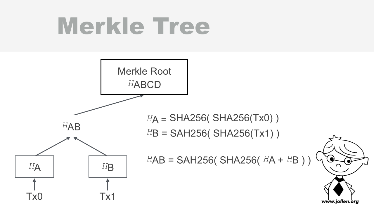
圖 1 生成 Merkle tree
Merkle tree 節點存放的是 double SHA-256 運算結果。如何將這 2 筆交易資訊,以 Merkle tree 來表示呢?以下是這一顆 Merkle tree 的生成過程。
將 Tx0 的本文(content)以 double SHA-256 進行雜湊運算,並將結果儲存在 HA,表示方法如下:
HA = SHA256( SHA256(Tx0) )
同理,再將 Tx1 進行 double SHA-256 運算,結果儲存於 HB:
HB = SAH256( SHA256(Tx1) )
SHA-256 的運算結果,是一個 64 bytes 的 HEX(十六進位)字串。在得到 HA 與 HB 後,就將這二個字串連接(concat)在一起,成為一個 64*2=128 bytes 的字串,這裡以 HA + HB 來表示。
再將 HA + HB 進行 double SHA-256 運算,結果儲存於 ```HAB``:
HAB = SAH256( SHA256( HA + HB ) )
HAB 就是 HA 與 HB 的父節點,這就是一個 3 個節點的 binary Merkle tree。
如果現在有 Tx0、Tx1、Tx2 與 Tx3 共 4 筆交易呢?完整的 double SHA-256 運算過程就是:
HA = SHA256( SHA256(Tx0) )
HB = SAH256( SHA256(Tx1) )
HC = SAH256( SHA256(Tx2) )
HD = SAH256( SHA256(Tx3) )

HAB = SAH256( SHA256( HA + HB ) )
HCD = SAH256( SHA256( HC + HD ) )

HABCD = SAH256( SHA256( HAB + HCD ) )
最後得到的 binary Merkle tree 就是圖 2。
Node.js 開發者不一定要自行實作 Merkle tree 演算法,網路上能找到開放源碼的實作。在 GitHub 上可以找到 Merkle 模組,這是 JavaScript 的 Merkle tree 實作,並且支援 SHA-256 在內的多種 hash algorithm。
先安裝 Merkle 模組:
$ npm install merkle --save
接著引入 merkle 模組:
var merkle = require('merkle');
建立 root node,並指定使用 SHA-256 演算法:
var merkleRoot = merkle('sha256');
宣告幾筆交易資訊,例如:
// 建立一筆新的交易紀錄
var tx = ['Created by Jollen'];
交易的內容,現階段可任意填寫。例如,如果有 4 筆交易資訊:
// 建立 4 筆新的交易紀錄
var tx = ['a', 'b', 'c', 'd'];
現在只是練習 Merkle tree 的生成,暫時還沒有定義交易的資料結構,所以填寫任意內容即可。
呼叫 async 函數,傳入所有交易資訊來建立 Merkle tree:
merkleRoot.async(tx, function(err, tree){
});
透過 Callback 函數來取得 Merkle tree。根據 Merkle 官方文件的說明,可以呼叫 tree`` 物件的 root``` 函數,來取得 Merkle root 的 Hash 值。以下是完整的範例列表:
var merkle = require('merkle');
var merkleRoot = merkle('sha256');

// 建立一筆新的交易紀錄
var tx = ['a', 'b', 'c', 'd'];

merkleRoot.async(tx, function(err, tree){
    console.log( tree.root() );
});
結出結果:
AB4587D9F4AD6990E0BF4A1C5A836C78CCE881C2B7C4287C0A7DA15B47B8CF1F
如圖 2 所示,Merkle tree 是 binary tree(二元樹),以 4 筆交易量來看,總計會有 6 個節點(nodes),並且「高度」為 3。這個高度稱為 level。
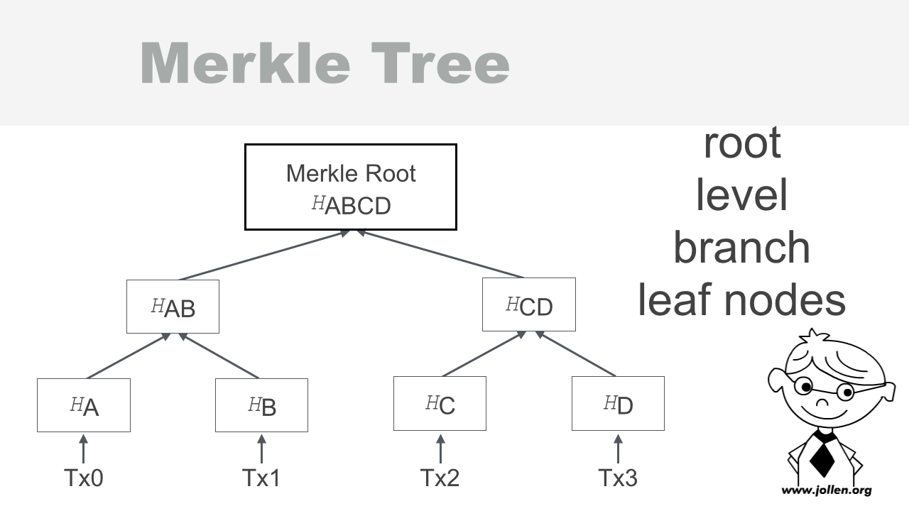
圖 2 Merkle Tree 的 depth 為 2
這是一個 levels 為 3 的 Merkle tree,排除 leaf nodes 後的高度稱為 depth。所以:
HA 與 HB 稱為 leaf nodes延續上述範例,取得該 Merkle tree 的 depth 與 levels:
merkleRoot.async(tx, function(err, tree){
    console.log( tree.root() );
    console.log( tree.depth() );
    console.log( tree.levels() );
});
結出結果:
AB4587D9F4AD6990E0BF4A1C5A836C78CCE881C2B7C4287C0A7DA15B47B8CF1F
2
3
此外,呼叫 level 函數,可以取得指定 level 的所有節點,例如:
merkleRoot.async(tx, function(err, tree){
    console.log( tree.level(1) );
});
輸出結果:
[ '6A20F2EE7789E6BB7F404CC2DD729FF308B724D904F6A455B74D4851ADE5AECB',
  'A99E82F486656840A790C0EF6024D2C02359DE7674A587562FEB81C8970F24DD' ]
如圖 2 所示:
如果要顯示所有的節點,要怎麼修改程式碼呢?答案如下:
merkleRoot.async(tx, function(err, tree){
    // 印出所有節點
    for (i = 0; i < tree.levels(); i++) {
        console.log( tree.level(i) );
    }
});
實際撰寫程式,來觀察 4 筆交易資訊的 Merkle tree:
var merkle = require('merkle');
var merkleRoot = merkle('sha256');

// 4 筆交易資訊
var tx = ['a', 'b', 'c', 'd'];

merkleRoot.async(tx, function(err, tree){
    // 印出所有節點
    for (i = 0; i < tree.levels(); i++) {
        console.log( tree.level(i) );
    }
});
輸出結果:
[ 'AB4587D9F4AD6990E0BF4A1C5A836C78CCE881C2B7C4287C0A7DA15B47B8CF1F' ]
[ '6A20F2EE7789E6BB7F404CC2DD729FF308B724D904F6A455B74D4851ADE5AECB',
  'A99E82F486656840A790C0EF6024D2C02359DE7674A587562FEB81C8970F24DD' ]
[ 'CA978112CA1BBDCAFAC231B39A23DC4DA786EFF8147C4E72B9807785AFEE48BB',
  '3E23E8160039594A33894F6564E1B1348BBD7A0088D42C4ACB73EEAED59C009D',
  '2E7D2C03A9507AE265ECF5B5356885A53393A2029D241394997265A1A25AEFC6',
  '18AC3E7343F016890C510E93F935261169D9E3F565436429830FAF0934F4F8E4' ]
為了幫助學習,圖 3 以視覺化的方式,來呈現這個範例的結果。

圖 3 視覺化 Merkle Tree
現在,你學會了如何使用 Node.js 來生成 Merkle tree,並且也更進一步了解 Merkle tree 的結構。
My paper titled “Flowchain: A Distributed Ledger Designed for Peer-to-Peer IoT Networks and Real-time Data Transactions” has been accepted by the 2nd International Workshop on Linked Data and Distributed Ledgers, as co-located at ESWC 2017, taking in place in Portoroz, Slovenia in May 2017. The paper proposes Flowchain, an open source distributed ledger programming framework, for peer-to-peer IoT networks and real-time data transactions.
Also, Flowchain proposes Virtual Blocks that provides a new blockchain data structure design to ensure the real-time data transactions. This paper also proposes a software architecture that provides peer-to-peer IoT networking and interoperable IoT application framework.
UPDATE: The paper can be download at the LD-DL workshop website.
Real-time Sensor Dashboard: Get Started with WebSockets, CoAP and Web of Things
The Web of Things (WoT) provides an Application Layer that simplifies the creation of Internet of Things applications1. WoT reuses existing web technologies, such as REST, HTTP, Websockets, CoAP and etc. 1.
This project aims to architect the Web of Things for wireless sensor networks.

The wireless sensor network is built from "nodes"2. A node in a sensor network is capable of gathering information and communicating with other nodes.
Figure-1: Wireless Sensor Network (Source: https://en.wikipedia.org/wiki/Wireless_sensor_network. License: Public Domain)
One of the simple topologies of the wireless network network is Star Network3.
Figure-2: Star Network (Source: https://en.wikipedia.org/wiki/Star_network. License: CC BY-SA 3.0)
In a star network, every node is connected to Gateway Sensor Node. A node in a star network will gather sensory information and send it to Gateway Sensor Node. We will use star network to architect the Web of Things in this project.

Figure-3: Goal of 201-web-of-things-dashboard
Figure-3 is a simple Web of Things architecture. In the figure:
Some technical details:
We will implement "Endpoint", "Proxy", "Node" and "Dashboard" in sequence.
The following steps show that how to deploy "Endpoint" to Azure web service.
Please change your working directory to this project.
$ cd <your-path>/devify-server/templates/201-web-of-things-dashboard
The project structre is as the following.
.
├── README.md
├── esp8266
│   └── coap-temperature.lua  The sample code of "Temperature Node"
├── package.json
├── server.js                 The sample code of "Endpoint"
└── server.proxy.js           The sample code of "Proxy"
We will deploy this project to Azure App Service. Azure App Service will run server.js automatically after we finish deploying our project.
You may need to visit Microsoft Azure if you want to know more about Microsoft Azure, or you have to sign up a new Azure account.
It's suggested that you read App Service if it's the first time to use App Service of Microsoft Azure.
$ npm install azure-cli -g
You must login to Azure in advance:
azure login
Then use the command line to create an Aure site:
azure site create --git
Input your site information at the prompt mode. This is an example:
$ azure site create --git
info:    Executing command site create
help:    Need a site name
Name: devify-temperature
+ Getting locations
+ Getting sites
+ Getting locations
help:    Choose a location
  1) East Asia
  2) North Europe
  3) West Europe
  4) Southeast Asia
  5) West US
  6) East US
  7) Japan West
  8) Japan East
  9) South Central US
  10) East US 2
  11) North Central US
  12) Central US
  13) Brazil South
  : 7
info:    Creating a new web site at devify-temperature.azurewebsites.net
-info:    Created website at devify-temperature.azurewebsites.net
+
info:    Executing `git init`
info:    Creating default iisnode.yml file
info:    Initializing remote Azure repository
+ Updating site information
info:    Remote azure repository initialized
+ Getting site information
+ Getting user information
info:    Executing `git remote add azure https://[email protected]/devify-temperature.git`
info:    A new remote, 'azure', has been added to your local git repository
info:    Use git locally to make changes to your site, commit, and then use 'git push azure master' to deploy to Azure
info:    site create command OK
Please append --git option to the command line. This option could make Azure CLI to add the remote git of our new created site to local project. We will use git to deploy our site.
After finishing creating site, remember the name of your site. Please looking for the Created website at message line to get your endpoint name.
The endpoint name is devify-temperature.azurewebsites.net in this example.
Run the command line to create credentials (the username and password):
azure site deployment user set
This is an example:
$ azure site deployment user set
info:    Executing command site deployment user set
Git username: jollen
Git password: *********
Confirm password: *********
+ Setting user credentials
info:    site deployment user set command OK
Use git to commit and push your project files to web site:
$ git add --all
$ git commit -m 'deploy to azure'
$ git push azure master
The is an example:
$ git add --all
$ git commit -m 'deploy to azure'
$ git push azure master
Password for 'https://[email protected]':
fatal: Authentication failed for 'https://[email protected]/devify-temperature.git/'
Moko365de-iMac:201-web-of-things-dashboard apple$ git push azure master
Password for 'https://[email protected]':
Counting objects: 10, done.
Delta compression using up to 2 threads.
Compressing objects: 100% (8/8), done.
Writing objects: 100% (10/10), 5.16 KiB | 0 bytes/s, done.
Total 10 (delta 1), reused 0 (delta 0)
remote: Updating branch 'master'.
remote: Updating submodules.
remote: Preparing deployment for commit id '0f244b55bf'.
remote: Generating deployment script.
remote: Generating deployment script for node.js Web Site
remote: Generated deployment script files
remote: Running deployment command...
remote: Handling node.js deployment.
remote: KuduSync.NET from: 'D:\home\site\repository' to: 'D:\home\site\wwwroot'
remote: Deleting file: 'hostingstart.html'
remote: Copying file: '.gitignore'
remote: Copying file: 'iisnode.yml'
remote: Copying file: 'package.json'
remote: Copying file: 'README.md'
remote: Copying file: 'server.js'
remote: Copying file: 'server.proxy.js'
remote: Copying file: 'esp8266\coap-temperature.lua'
remote: Using start-up script server.js from package.json.
remote: Generated web.config.
remote: The package.json file does not specify node.js engine version constraints.
remote: The node.js application will run with the default node.js version 4.2.3.
remote: Selected npm version 3.5.1
remote: ....
.
.
remote: Finished successfully.
remote: Running post deployment command(s)...
remote: Deployment successful.
To https://[email protected]/devify-temperature.git
 * [new branch]      master -> master
To enable web sockets:
azure site set -w
This is an example:
$ azure site set -w
info:    Executing command site set
Web site name: devify-temperature
Web site slot [enter for none]:
\ Updating site config information
The simplest way to run "Proxy" is to use the laptop.
$ cd <your-path>/devify-server/templates/201-web-of-things-dashboard
$ npm install
$ export ENDPOINT=devify-temperature.azurewebsites.net
$ export HOST=192.168.1.100
$ export PORT=8000
$ node server.proxy.js
There are three variables for configuration options.
Open coap-temperature.lua file. Fill in with the WiFi hotspot name and password.
wifi.sta.config("<SSID>", "<PASSWORD>")
Then, please find this line, fix the IP address and listening port.
uri="coap://192.168.1.100:8000/object/5550937980d51931b3000009/send"
The "Proxy" and "Node" should be connected to the same WiFi station.
Please install Devify CLI to speed up setup "Dahsboard".
$ npm install devify-cli
Download a sample dashboard.
$ devify ui ui-moving-line
It will download ui-moving-line repo, a simple web frontend of moving line chart.
Change directory to ui-moving-line, and start a web server to serve ui-moving-line.
$ cd ui-moving-line
$ devify serve ./
Open your browser with http://localhost:3000/index.html#testman/wot.city/temperature. You will immediately see a demo.
The URL format is as index.html#<DeviceID>/<Endpoint>/<Y-Axis-Key>.
This is an example:
index.html#5550937980d51931b3000009/devify-temperature.azurewebsites.net/temperature


Decentralized 物聯網架構,需要 P2P 的通訊架構。
在 IoT 架構裡,實作 Peer-to-Peer (P2P) 網路有技術上的挑戰嗎?實作 Peer-to-Peer IoT Networking 的目標,是為了讓 IoT Devices 簡能建立 P2P 架構的通訊方式,這就是技術上的挑戰了。讓 IoT Devices 能形成一個 P2P 網路,技術上似乎不太困難;不過,如果更深入技術細節來討論,就會發現許多學問。
第一、應用層的考量。IoT 裝置間必須以 Application Layer Protocols 來通訊,例如:HTTP。所以,我們需要能在 IoT 裝置上運行一個「Application Server」,也就是說,必須有一個「Programming Framework」,然後才能在 IoT 裝置上開發這個 Application Server。這裡所提及的 Programming Framework,可以是 IoT 作業系統,或是 Middleware;但其實重點在於,為什麼 P2P 的 IoT Networking,要使用最上層的 Application Layer Protocols;這是一個值得探索的有趣議題。
第二、異質硬體的考量。Flowchain 計畫的早期,是從打造一個 Web of Things Framework [1] 起步,這個軟體框架的目的,是以 JavaScript 實作一個 IoT Application Server 的開發框架,有了這個框架,就能達到二個目的:
如果異質硬體都能具備 JavaScript runtime,同樣的 IoT Application Server 就能佈署並運行在這些硬體上。因為 Node.js、JerryScript 等技術被帶入到這些硬體上,這個想法現在有了很高的可行性。
IoT Blockchain 並非一個主題,而是一套 IoT Architecture,當中的 P2P Networking,有賴於一個 IoT Application Server 的框架來實現。
[1]: Web of Things Implementations, https://www.w3.org/WoT/IG/wiki/Implementations
Servient 概念非常簡單:IoT Device 能同時扮演 Client 與 Server 的角色。這個 Client + Server = Servient 的觀念,是 Decentralized 與 P2P 非常重要的底層技術。
從 IoT Architecture 的觀念來說,並不是去辨別(identify)每一個物聯網裝置要扮演 Client 或 Server 哪一個角色,而是來開發一個能讓裝置扮演 Client + Server 角色的軟體。
為什麼需要 Servient 這樣的架構呢?這個問題,可以很容易用圖 1 來解答。

圖 1:IoT Servient
當 Device A 想要以 WebSocket 來傳送資料到 Device B 時:
當 Device B 想要以 CoAP 來傳送資料到 Device C 時:
以上述的 Use Case 來說:
Servient 並不是一個很普遍的架構觀念,過去在一些技術文件上也能偶然看到 Servient 的觀念;但是,Servient 在 IoT 領域被正式提及,則是在 ISWC 2016 國際研討會上。在 ISWC 2016 上,Soumya Kanti Datta 在 Semantic Web meets Internet of Things and Web of Things 的 Tutorial 上,正式提到 WoT Servient 的觀念。
近期,在 Web of Things (WoT) Architecture: Unofficial Draft 文件中,已經將 WoT Servient 編入 Terminology。隨著 WoT 在今年(2017)已經正式由 IG(Interest Group)轉為 WG(Working Group),未來 WoT 也會正式列入這個架構。
當 IoT Device 能以 Servient 的形式運作,IoT Device 間的「互聯網」:互相聯結的 IoT 網路,就可以是 Client-Server 架構、Peer-to-Peer 架構或是 Distributed 架構。
關於 IoT Servient 的技術,在 Devify 專案裡有完整的實作。Devify 是我過去在研究物聯網區塊鏈時做開發的底層 WoT 系統。
由聯發科所開發的 LinkIt 7697 物聯網平台,提供一個稱為 MCS Lite 的私有雲方案;MCS Lite 裡就使用到我所開發的 Devify 框架。也就是說,LinkIt 7697 + MCS Lite 還有更多 IoT 的完法喔。
已發佈至 Jollen's Blog
Unikernel 是一個很有趣的概念。不久前 Docker 收購 Unikernel Systems[1] 是很多人對它的第一印象,台灣的新聞媒體將 Unikernel 翻譯為「無核化」或「去核化」;不過,Unikernel 並「不是」要消滅作業系統核心,當然也不是要去除作業系統核心;相反地,作業系統核心技術,將更顯重要。
相較傳統的作業系統核心(conventional OS),Unikernel 的作業系統核心是以「Library」的形式實作 。技術上來說,Unikernel 可以說是一個「Library OS」的概念。
Unikernel 的做法(implementation)是將應用程式(applications)、相關模組(modules)與 library OS 打包(construct)成一個 image 檔。這樣做的目的,是希望將目標系統(target image)儘量簡化;簡化的目的,是縮小 images 的大小(image size)。
根據維基百科上的解釋[2]:
These libraries are then compiled with the application and configuration code to build sealed, fixed-purpose images (unikernels) which run directly on a hypervisor or hardware without an intervening OS such as Linux or Windows.
簡單來說,打包出來的 images 檔就稱為「Unikernel」。這個打包的過程,會將 library OS 編譯到應用程式裡,因此,製作 unikernel image 也需要配套工具。
Unikernel 並不是要去除作業系統。所謂的「無核化」的「核」,更精準的解釋應該是去掉 conventional OS 的「核(kernel)」,改採 library OS 的「核」。
專研作業系統與編譯器的工程師,不但沒有身價眨值的問題,還可能會倍數增值呢。為什麼學習作業系統又更重要了呢?因為 Unikernel image 是一種特定用途的 image file,這種 image file 也稱為 immutable VM image。
Immutable image 裡面的 library OS 讓 unikernel image 能直接(directly)在虛擬機上(hypervisor)運行,而不需要透過像是 Linux 或 Windows 的 conventional OS[2]。實作這個 library OS 需要對作業系統、微處理器、虛擬機、編譯器與 software stacks 有綜合的知識。
Unikernel 是一個 image file,也是一種 immutable image。它的用途單一不變(immutable),Unikernel 的「Uni」正能表達它的理念。Unikernel 自然有許多不同的實作;針對不同的應用程式(applications)甚致是不同的雲端佈署架構,也需要更多單一的 library OS。
受到 jserv 一直在自幹編譯器[3]的激勵,新的一年(2016 猴年)就幫自已定了一道作業:期許在新的一年,也可以自已做一個 Unikernel。不過,因為 Unikernel from scratch 的目標有點遠大,所以:
近幾年一直是 JavaScript 的愛好者,所以找了 runtime.js 做為研究目標。Runtime.js 提供一個稱為 * runtimeify* 的編譯器,可以將 JavaScript 應用程式,打包為 ramdisk image,並透過 initrd 啟動。第一階段的學習紀錄,都會發佈在 jollen/simple-iot-runtime
沒想到 Embedded Linux 也能有這樣的面貌,這是一種有點熟悉又有些陌生的奇妙感覺。隨著 Node.js 的發展,以及 frontend 模組化(JavaScript modules)技術的進步,出現了 Browserify 技術,今天還被運用在 Unikernel 概念上,只能說 JavaScript 無極限。
Runtime.js 是一個開源的 library OS 實作,裡面包含二個 component [4]:
Runtime.js 的 OS kernel 採用 V8 JavaScript engine,整體來看,Runtime.js 提供了一個優雅的 JavaScript Unikernel 技術方案。
[1] Unikernel Systems Joins Docker, https://blog.docker.com/2016/01/unikernel/
[2] Unikernel, https://en.wikipedia.org/wiki/Unikernel
[3] 從無到有開發 C 編譯器, https://goo.gl/aqBw9R
[4] Runtime.js, https://github.com/runtimejs/runtime
[5] https://github.com/jollen/simple-iot-runtime
已發佈至 Jollen's Blog
以下步驟參考自 Runtime.js 官網 的說明,目標是初始化一個新的 Runtime.js 專案。請參考 Getting Started 上的環境安裝說明。
要使用 Runtime.js 必須安裝 Node.js 執行環境,以下步驟以 Mac 環境為主,Node.js 的版本為 v4.2.6。
Runtime.js 仍是一個發展中的開源計畫,目前的發展狀態如下:
即便 Runtime.js 還是處於這麼早期的階段,但實作簡單的 IoT cloud VM image 問題並不大。以下是使用 runtime.js 製作 unikernel image 的準備工作說明。
安裝 QEMU VM 做為 Runtime.js 的執行環境。以 Mac 為例,使用 homebrew 安裝 qemu:
$ brew install qemu
Runtime.js 目前僅支援 KVM。
使用 npm 建立新的 Node.js 專案:
$ mkdir simple-iot-runtime
$ cd simple-iot-runtime
$ npm init
這次的學習計畫,將不使用 Express。如果要實作 REST API 的話,後續就要實作一個小型的 URL router。
安裝 Runtime.js 的 core library:
$ npm install runtimejs --save
Runtime.js 提供二個命令列工具(CLI):
$ sudo npm install runtime-cli -g
$ sudo npm install runtimeify -g
Browserify 原本是用給 frontend 開發使用的工具,讓 frontend 的 JavaScript 程式碼,也能以 require() 的風格引入相依模組。現在被應用於 Runtime.js 專案中。
將主程式 index.js 打包(bundle)成 initrd 檔案:
$ runtimeify index.js -o initrd
使用 runtime-cli 啟動製作出來的 initrd:
$ runtime start

上述步驟得到的 initrd 就是一個 unikernel image。runtime-cli 是 qemu 的 wrapper,測試方式是使用 runtime-cli 啟動 qemu,並載入 initrd 檔案。initrd 是 runtime.js 預設的 unikernel 檔案。
雖然 unikernel 的檔名是 initrd,但這與 GNU/Linux 上的 initrd(init process)是完全不同的實作。Runtime.js 所製作的 initrd,其實就是 browserify 所編譯出來的 JavaScript 應用程式。
為了在 NodeMCU 上進行 WoT 實驗,日前開啟了一個小型的專案 node-wot,node-wot 將會持續小幅修改 nodemcu-firmware,以做為 WoT 的實驗用 firmware。
目前的主要修改內容,是將 NodeMCU firmware 裡的 libcoap 更換為 Contiki OS 的 er-coap-13 實作,並且只保留了 CoAP client。主要的原因如下:
現階段,僅將 ESP8266 做為 data push object,並不做為 CoAP server,因此只保留 CoAP client 的實作。主要考量是節省 RAM + ROM 的空間(ESP8266 的 iram1_0_seg + irom0_0_seg)。
er-coap-13 的完整 API 設計,是 node-wot 專案的重要考量。例如,要建立一個新的 CoAP 封包,只要呼叫 coap_init_message() 函數即可:
// 引入 er-coap-13 APIs
#include "er-coap-13.h"
#include "er-coap-13-transactions.h"

// 宣告 CoAP packet
coap_packet_t request[1];

// 將 CoAP packet 初始化為 COAP_TYPE_CON 類型,並使用 HTTP POST
coap_init_message(request, COAP_TYPE_CON, COAP_POST, 0);
要初始化 CoAP headers,例如:填寫 CoAP header 的 Uri Path 與 Uri Host,只需要這樣寫:
coap_set_header_uri_path(request, 'object/123456/send');
coap_set_header_uri_host(request, 'wot.city');
要加入 payload(本文),也只要這樣寫:
const char *payload = "{}";
coap_set_payload(request, (uint8_t *)payload, strlen(payload));
最後也只要呼叫不到 5 個 APIs,就可以將 CoAP 封包送出。
er-coap-13 有更好的 abstraction level,可以隱藏所有 CoAP 標準的技術細節。
node-wot 上的 er-coap-13 做過微幅修改,以及完整的測試,可保證 CoAP requests 不會消耗 Heap 空間。Heap 空間若持續減少,會發生記憶體不足的現象,Lua 程式會 crash。
node-wot 的修改並不影響 Lua programming model,因此 Lua 程式可同時在 nodemcu-firmware 與 node-wot 上執行。
以下是 2015 年 12 月 8 日在 ESP8266 IoT Workshop 上使用的 Lua 範例(搭配 node-wot firmware 使用)。
以 HTTPD 做為學習 Lua 的 "Hello, World"。
-- Select IO - GPIO4
outpin=4
gpio.mode(outpin,gpio.OUTPUT)
gpio.write(outpin,gpio.HIGH)

function power(stat)
  if stat=="ON"  then gpio.write(outpin,gpio.HIGH)
    return
   end
  if stat=="OFF" then gpio.write(outpin,gpio.LOW)
    return
   end
end

-- Print IP address
ip = wifi.sta.getip()
print(ip)

-- Configure the ESP as a station (client)
wifi.setmode(wifi.STATION)
wifi.sta.config("JY", "1234567654321")
wifi.sta.autoconnect(1)

-- Create a server
-- and set 30s time out for a inactive client
sv = net.createServer(net.TCP, 30)

-- Server listen on 80
-- Print HTTP headers to console
sv:listen(80,function(c)
    c:on("receive", function(conn, payload)
        print(payload)

        if (string.find(payload, "GET /power/on") ~= nil) then
            power("ON")
        elseif (string.find(payload, "GET /power/off") ~= nil) then
            power("OFF")
        end

        conn:send("HTTP/1.1 200 OK\n\n")
        conn:close()
    end)
end)
以 CoAP request 做為學習 IoT 的 "Hello, World"。
-- Print IP address
ip = wifi.sta.getip()
print(ip)

-- Configure the ESP as a station (client)
wifi.setmode(wifi.STATION)
wifi.sta.config("JY", "1234567654321")
wifi.sta.autoconnect(1)

-- Print IP address
ip = wifi.sta.getip()
print(ip)

-- Create a CoAP client
cc = coap.Client()

-- Make a POST request
uri="coap://127.0.0.1:8000/object/12345678/send"

tmr.alarm(0, 1000, 1, function()
    cc:post(uri, "{\"temp\":20}\r\n")
end)
最後是一個 CoAP-LWM2M Broker 的範例。需搭配 WoT.City 專案使用。
- Print IP address
ip = wifi.sta.getip()
print(ip)

-- Configure the ESP as a station (client)
wifi.setmode(wifi.STATION)
wifi.sta.config("JY", "1234567654321")
wifi.sta.autoconnect(1)

-- Print IP address
ip = wifi.sta.getip()
print(ip)

-- Create a CoAP client
cc = coap.Client()

-- Make a POST request
uri="coap://172.20.10.4:8000/object/12345/send"
cc:post(uri, "{\"temp\":30}\r\n")

-- Register LWM2M object
registry="coap://172.20.10.4:8000/75000/1/create"
cc:post(registry, "{}\r\n")
這個範例需要搭配一個 *LWM2M broker server * 來使用:
這個範例,假設 NodeMCU 僅做為 CoAP client 使用,因此 node-wot 目前並沒有移植 er-coap-13 的 CoAP server 實作。
此外,考量硬體限制(ROM 與 RAM 大小),也沒有移植 LWM2M 程式庫至 node-wot。
OMA LWM2M 建構在 CoAP 協定層之上,在這次的工作坊裡,展示了如圖 1 的佈署(deploy)策略。
以下是這個佈署策略的簡要說明:
延續 在 NodeMCU 上使用 er-coap-13 的介紹,使用 er-coap-13 來建立 CoAP 封包的完整寫法如下:
// 引入 er-coap-13 APIs
#include "er-coap-13.h"
#include "er-coap-13-transactions.h"

int main()
{
// 宣告 CoAP packet
coap_packet_t request[1];

// 將 CoAP packet 初始化為 COAP_TYPE_CON 類型,並使用 HTTP POST
coap_init_message(request, COAP_TYPE_CON, COAP_POST, 0);

// 初始化 CoAP headers,填寫 CoAP header 的 Uri Path 與 Uri Host
coap_set_header_uri_path(request, 'object/123456/send');
coap_set_header_uri_host(request, 'wot.city');

// 加入 payload(本文)
const char *payload = "{}";
coap_set_payload(request, (uint8_t *)payload, strlen(payload));
}
CoAP 封包必須指定 Message ID(MID),MID 有許多用途,例如:用來做 Duplicate Rejection1。取得 MID 的方式是呼叫 er-coap-13 的 coap_get_mid 函數:
request->mid = coap_get_mid();
為什麼區塊鏈是 Web 3.0 的概念?因為 Web 3.0 有一個重要的概念,就是 P2P Internet。區塊鏈除了能為 Web 3.0 提供 P2P Internet 基礎建設外,也因為區塊鏈本身「天然特性」,還能提供 Web 3.0 所需的 Trusted Computing 與 Cryptography 技術。
Trusted computing 與 cryptography 在 IoT 領域,能提供絕佳的 Data security 與 Data privacy 環境。因此,一個建立在 Web 概念與 P2P 網路之上,並且能提供 Data security 與 Data privacy 環境的物聯網架構,就是物聯網區塊鏈(Blockchain IoT)的主要研究方向。
Flowchain 計畫就是為此生。由 Linux Foundation 主辦的 LinuxCon + ContainerCon + CloudOpen (LC3) 今年(2017)首次到北京舉辦,而且也設立了區塊鏈專場,利用這個難得的機會,投稿了今年 LC3 的 Blockchain Track;很幸運地得到 reviewers 的青睬,順利得到一個珍貴的演講機會。
Filecoin 的 ICO 將在 1 天後結束。ICO 正式受到各國政府的重視(與監管)絕對是個好事,因為政府的介入,正好加速清理詐騙與「動機不明」的 ICO 計畫;同時,也能為真正想用於投資與建立 Foundation 的 ICO 計畫,建立起保護傘。
ICO 在這波 ICO 亂象結束後,未來將更為成熟;ICO 也將走向 Accredited-Only Sale 的模式,
(TBD)
Web of Things 是 W3C 的一個興趣小組,它的目的是以現有的 Web 技術,來思考 IoT 的設計與架構。關於 Web of Things 的概念說明,在 W3C 上有一篇 Building the Web of Things 的文章,為 Web of Things (WoT) 的源起與哲學,做了很好的說明。
WoT.City 是一個研究型的開源計畫,目的是實作 W3C Web of Things (WoT)。WoT.City 主要在處理 Connectivity,例如:WebSocket、CoAP 與 Thing Description 等。WoT.City 是 Connecitivity Layer,目前它已經打包成 wotcity.io 模組,但是你不需要直接使用 wotcity.io 模組。
wotcity.io 被封裝為 devify-server 模組,devify-server 是一份 IoT server boilerplate,這是什麼呢?簡單說,就是一套給 IoT 用的伺服器程式模板,你可以用 devify-server 很容易寫出一個「負責收集感測器資料」的 IoT server。
這套 IoT server 可以執行在 Desktop、Server 或 IoT device 上,它使用的是 Nodoe.js 技術,這表示只要有 Node.js 執行環境的硬體,都可以成為 devify-server 的執行環境。架構上,devify-server 封裝了 wotcity.io,並且負責 Event Handling、Broker Server 與 Serverless 的角色。

上圖是 WoT.City 的架構,也是 WoT.City 的理念:
目前已經有許多 Web of Things 的開源項目,你可以在這裡找到一份 Web of Things Implementations 的清單,這份清單整理 W3C Web of Things 的相關計畫。
另外,除了 WoT.City 與 Devify 外,整體 WoT.City 計畫中,預計還有一個 Flowchain 項目。Flowchain 提供 flow-based programming 的 IoT 應用開發模式,同時也支援 Blockchain 與 P2P。經由 Flowchain 項目,讓 WoT.City 能實現 Decentralized IoT 的構想。
有了 Web of Things 初體驗後,應該會對 React 元件與 IoT 的關係有了好奇心。React 在 IoT 的全端開發,最簡單的使用情境就是:製作能接收 Server Push 的 React 元件。
另外,還有一件事情也吸引我的目光:Flux 模式。把 Flux 模式用在這裡,似乎是再好不過了,因為,根據 Flux 模式的設計:我們可以用 Actions 來調用 REST API。把思路放大一下:Actions 是用來與 Backend 互動的單元,運用這個觀念,或許可以實現一個簡單的 Flux 程式庫,並在 Action 裡建立與 WebSocket Server 的連線。
一個簡單的範例由此而生。先下載與運行 react-websocket-biolerplate 範例:
$ git clone https://github.com/jollen/react-websocket-biolerplate.git
$ cd react-websocket-biolerplate
$ npm install
$ gulp compile
使用瀏覽器開啟 dist/index.html 文件即可,你會看到來自 wot.city 服務器的即時數據。
src/App.jsx,並修改 server propgulp compile 命令重新編譯文件這個範例的實現觀念非常簡單:
react-websocket-flux 模組,這是一個簡單 Flux 實現react-websocket-flux 裡後,透過 onMessage 接收即時數據Flux 模式運用在這幾個地方:
WebsocketActions.connect() 與 WebSocket 服務器建立連線onMessage 事件回調函數componentDidMount lifecycle 裡調用 WebsocketStore.addMessageListener 註冊 onMessage callbackcomponentWillUnmount lifecycle 裡調用 WebsocketStore.removeMessageListener 解除註冊以下是完整的實現步驟說明。根據此,也能為現有的 React 元件注入 WebSocket 功能。
import React, { Component } from 'react';
import { render } from 'react-dom';

// 1. 引入 'react-websocket-flux'
import { WebsocketStore, WebsocketActions } from 'react-websocket-flux';

export class MyComponent extends Component {
    constructor(props, context) {
        super(props, context);

        // 2. 初始化 this.state
        this.state = {
            temperature: -1
        };

        // 3. WebSocket 的 'onMessage' callback
        this.onMessage = this.onMessage.bind(this);

        // 4. 連線到 WebSocket Server
        WebsocketActions.connect(this.props.server);
    }

    componentDidMount() {
        // 5. 將 'onMessage' 註冊到 react-websocket-flux
        WebsocketStore.addMessageListener(this.onMessage);
    }

    componentWillUnmount() {
        // 將 'onMessage' 從 react-websocket-flux 解除註冊
        WebsocketStore.removeMessageListener(this.onMessage);
    }

    onMessage(data) {
        // 6. Deserialize: 從 Server 推送過來的 JSON data 取出資料,並放入 this.state
        this.setState({
            temperature: data.temperature
        });
        console.log(data)
    }

    render() {
        return (
            <div>
                <h1>{this.state.temperature}</h1>
            </div>
        );
    }
}
在 React 應用程式裡,引入你的元件使用:
server prop 指定 WebSocket 服務器 URIwss://wot.city/object/testman/viewer 測試數據範例片斷如下:
// 我的 React 元件
import { MyComponent } from './Component';

// 加入 server prop
render(
    <MyComponent server="wss://wot.city/object/testman/viewer">
    </MyComponent>,
    document.getElementById('content')
);
本文的完整範例 react-websocket-biolerplate.git。
Bitcoin mining 演算法,就是使用傳統的 SHA-256 函數,而 SHA-256 的優點,也好就是它的一個缺點。
SHA-256 函數是傳統的 hash 演算法,但是應用在區塊鏈系統時,有一個缺點。Bitcoin mining 演算法,就是使用傳統的 SHA-256 函數,而 SHA-256 的優點,也好就是它的一個缺點。
為了提升 SHA-256 的計算速度,工程師會利用行平行處理(parallelism)的技術。利用平行運算,大幅提升 SHA-256 的運算速度,這樣做不是很好嗎?
然而,這就是一個問題了。簡單來說,一個能平行化的演算法,就能使用硬體來做加速,例如,使用 GFP 或是 ASIC,這裡就是「弊端」所在了。從 Proof-of-Work 的觀點來看,「大家必須公平地做計算」,意思是說,因為 hash 值的運算是「decentralization」的架構,所以「大家的硬體最好一樣」。
Proof-of-work 的主要工作是 mining。此外,驗證交易的「可信度」,也是 proof-of-work 的一環。Proof-of-work 的工作不此於此,例如:miner 間的資料庫同步,也是包含在內。總之,proof-of-work 很忙。
這些 proof-of-work 的工作,是 miners 一起進行的,而不是由一個**伺服器(centralized)來統一運算,這就是 decentralization of trust 的觀念。
更簡單來看,這就是所謂的 decentralization(去中心化)架構。以 mining 來說,每個人都可以參與 hash 值的運算(大家都可以挖礦),所以,想「快一點」的人,就會使用 ASIC 挖礦機。可是,有些人是用自已的電腦來挖礦。
到這裡,問題就很清楚了:大家的硬體如果等級不同,挖礦就會「不公平」。
為了解決這個問題,科學家就想出了一個方法。這個方法非常簡單,首先,你不可能強制每個人都要買一樣的電腦才能挖礦,所以解決方式就要回歸演算法的本質:parallelism。
於是,科學家提出一種稱為 memory-hard function 的 hash 演算法觀念:一種不能或難以平行化的 hash 演算法。
這讓我想過幾年前的一個有趣故事。過去,多核心處理器開始後,開始有 Android 手機的製造廠,以「多核心手機」做為市場宣傳口號。這當然很好啊,「多核就是快」。但是,學軟體的人都知道一個道理,就是「軟體必須支援多核心」。如果你的軟體設計,本身就不是多核心架構,那就會像這支手機一樣:明明是 4 核心,但是開機後,其實只用了 1 個核心,另外 3 個核心被關閉(省電考量)了。
有了 memory-hard function 後,「挖礦」就理論上公平了,並且也能消息弊端。因為,就算有頂極的挖礦機,也會像這支多核心手機一樣:再強的硬體也很難加速軟體運算。
Memory-hard function 是怎麼做到這點的呢?上述的「一種不能或難以平行化的 hash 演算法」,其實是利用這個原理:降低平行處理的優勢。讓平行處理難有發揮的空間,這樣就能降低 GFP、FPGA 或 ASIC 控礦機的優勢了。
要消除平行處理的優勢,只要讓軟體是 memory intensive 即可。Memory intensive 是每天都會看到的現象:記憶體不足時、電腦變慢。
Memory-hard function 的原理就是這樣,在 hash 運算時,可以透過「亂塞一堆資料到記憶體」的方式,降低硬體的運算優勢。這就是 hash 演算法,就稱為 memory-hard function。
Argo2 是屬於 memory-hard function 的一種演算法,Blockchain 開發者會知道它,是因為 Argo2 在 2015 年,從 24 個參賽者中,拿下 PHC 競賽的優勝。
Argo2 可以取代傳統的 SHA-256 函數。如果想要知道原因的話,一般的說法就是:Argo2 沒辦法用 ASIC 挖礦機進行挖礦。
接下來,可以試著 fork 一份 block0 專案,導入 Argo2 演算法,並試著比較 Argo2 與 SHA-256 的挖礦困難度。
Chord 能運用在 Peer-to-Peer 的 IoT 網路,但是有些技術細節必須從軟體架構的層面解決。第一個會面的技術問題,就是「Churn」現象。
所謂的 Churn 現象就是:在 Peer-to-Peer 網路中,隨時都有節點(node)加入或離開。對於 Churn 的處理,要根據不同的 P2P 演算法來進行研究。Chord 如何處理 Churn 問題,以及 Handling Churn 的效能分析,過去已經有許多研究論文提出解決方法。
至於 Flowchain 區塊鏈 當然也有針對 Churn 進行研究。在 Flowchain 裡面,處理 Churn 現象的方式,是以擴充 Chord Protocols 的方式來進行處理;這方面的研究,已經撰寫成學術論文,並且被 AIoTAS 2017 接受並發表。
當 P2P 網路的節點,很頻繁地加入或離開時,這個網路稱為 High Churn Rates。如果 IoT Blockchain 無法有效處理 High Churn Rates 的問題,Data Transactions 的能力就會降低。例如,有資料需要交易處理時,就要經由 DHT 裡找到負責節點,但這個節點可能已經離開了。
IoT 裝置會離開 P2P 網路的原因,可能是 Wi-Fi 訊息不良,也可能是電量問題等其它問題;這和以 PC 為主的典型 P2P 網路非常不同。例如:PC 並非電池式裝置,因此 IoT 裝置的 Churn Rates 可能會因為電池因素而上升。又如,Wi-Fi 訊號問題,造成 P2P 網路中,經常有裝置會離線,這又是另一個造成 High Churn Rates 的因素。
關心 Blockchain、更別忘了 Web 3.0。IoT Blockchain 近期在台灣產業界受到不少關注。許多報導與活動,都在討論物聯網區塊鏈的機會與方向;我則是在 ESWC 發表 IoT Blockchain 的具體成果與程式碼。
ESWC (Extended Semantic Web Conference) 是歐洲主要的 Semantic Web 學術會議,今年在 Piran (斯洛維尼亞) 舉辦的 ESWC 2017 已經邁入第 14 屆。這次參加 ESWC 2017 全程 5 天的會議,學習來自各界的研究成果分享,非常有收獲。
在與 ESWC 2017 共同舉辦的 International Workshop on 2nd Distributed Ledger and Linked Data (LDDL) 上,我有一篇關於物聯網區塊鏈 (IoT Blockchain) 的論文被 Accept,因此有了 20 分鐘的機會,向大家簡報 Flowchain 計畫的目標。
另人興奮的是,一位來自 Standford 的教授,對於 Flowchain 的想法感到興趣;Chord 不是一個新的 DHT 技術,過去也有許多 Chord 的 fixed 與 extended 研究被提出,但對於利用 Chord 的 Distributed Data Store 這項「天然特性」來實作 Distributed Ledger,Flowchain 很可能是第一個提出這項應用的研究計畫。
在經過這段時間的 paper review 與現場討論後,準備開始進行 beta release 的 commits 了。目前 alpha 版本,將保留為 Proof-of-Concept 的版本,目前已經將程式碼發佈在 Github 上:
https://github.com/flowchain/flowchain-ledger
這個版本沒有太多的雕飾與抽像資料結構,所以可以很容易看出 Flowchain 的架構。接下來,在 7 月底前,將進入 beta commits,陸續將 evaluation code 重寫並提交;同時,也會開始進行商業化。
Semantic Web 另一個耳熟能詳的名字,叫做 Web 3.0;這次在 ESWC 2017 上,我發現幾個 Web 3.0 的共同研究方向。總結一下 Web 3.0 接下來可能的研究熱點:第一、對於 Data Streams 的支援。第二個多次被出的議題是 Security 與 Privacy;第三則是 Decentralized。
關於 Data Streams 的部份,透過延伸 RDF 以支援 Data Streams,是這次 ESWC 2017 不約而同的一個主題;因為過去大多著重在 Document-Oriented Data 應用,因此 Streaming Data 的研究相對較少。這個主題很明顯,開始受到特別關注了。
圖:會議酒店的海岸
Data Streams 又分為 Time-Series Data (aka Point-based) 與 Interval-based Data 二類;以這次大會選出的 Best Paper 為例,該論文就是針對 Time-Series Data 進行研究,並提出一套方法論 (Ontology),讓 Web 3.0 能分析即時交通資訊,以提升道路安全。
Flowchain 也提出一個以 Semantic Web 支援 Time-Series Database (TSDB) 的方法;這部份的程式碼,預計在 Flowchain v2.0 開始發佈。
最後,讓 Web 3.0 支援 Data Streams 很重要嗎?現在的 Machine Learning 已經很擅長分析 big “history” data 了;如果讓 Data 能更好的語意化 (Semantic),並打造一套好的 “RDF” Streams Store,就可以讓 Machine Learning 能更好地分析即時數據。這也是今年 ESWC 2017 的另一個重點。
Flowchain 目前處在 Proof-of-Concept 階段,後續計畫包含 TSDB(Time-Series Database)、去中心化的 IoT 通用框架(Decentralized and Generic IoT Programming Framework)以及混合區塊鏈的佈署案例(Hybrid Blockchain)。在商用化部份,目前已經開始搭配 Hyperledger Fabric 來提供一個 Edge Computing 與 IoT Blockchain 的實驗系統。所有的開源項目,以及最新進展,將會在 https://flowchain.io 上發佈。
混合區塊鏈(Hybrid Blockchain)的概念並不難懂:Private Blockchain + Public Blockchain。概括式地說,將私有鏈(Private Blockchain)與公有鏈(Public Blockchain)混合使用,就稱為混合鏈。這篇文章的目的,不是只談概括式的概念,而是要先從技術的角度來看混合區塊鏈。
從使用情境(Use Scenario)的角度來劃分,可以將區塊鏈(Distribued Ledger 的一種類型)分為 Permissioned 與 Permissionless 二種類型。
Permissioned 類型的區塊鏈,採取會員制度(Member Service),只有會員資格的組織或個人,才能參與該區塊鏈的運作,知名的 Hyperledger 就是屬於這類型的區塊鏈軟體(Distributed Ledger)。
因此,Permissionless 就是開放式(公開)的區塊鏈系統,任何人都可以加入到這個網路。技術上來說,這二種不同類型的區塊鏈系統,共識機制(Consensus)與適合場景(Use Case)都有很大的不同。知名的 Nakamoto Blockchain(就是 Bitcoin 的區塊鏈系統)就是屬於 Permissionless 區塊鏈。
技術上,「參與該區塊鏈的運作」,指的是節點(Node)是否具備加入(Join)區塊鏈網路(Networking)的權限。因此,更為精確的說法,應該是 Permissioned Networking 與 Permissionless Networking。建構在 Permissioned Networking 系統上的區塊鏈,稱為 Permissioned Blockchain。
總結來說,區塊鏈就分別 Permissionless Public Blockchain 與 Permissioned Private Blockchain 二大類。不過,只要有想法就能做的出來;這是一個技術驅動的世界。目前,也有 Permissioned Public Blockchain 的區塊鏈技術。
這次在「LinkIt Smart 7688 與 Wio Link(ESP8266)技術沙龍」活動上,閃電展示了如何使用 Wio Link 自製 GoPro 的 Remote 控制器,整個過程只需要大約 30 分鐘,以下分享製作方法。
本專案的技術原理非常簡單:
本文使用 Wio Link 或 NodeMCU 開發板,並以 Lua 來撰寫 HTTP request 程式碼。如果改用 Node.js 來實作 HTTP request,就可以改用近期火紅的 MediaTek LinkIt Smart 7688 (Duo) 開發板來製作 GoPro 控制器。
下載 GoPro Studio 安裝後,將 GoPro 連接到電腦。GoPro Studio 會自動更新 GoPro firmware。
使用 NodeMCU 的開發者可忽略這個步驟。
Wio Link 預載 Seeed Stduio 專門打造的 firmware,可搭配 Wio Link App[1] 快速打造 IoT application。在這個小專題裡,我們會使用 Lua 來撰寫簡單的 GoPro 控制器,因此要更換為 NodeMCU firmware。
更新 NodeMCU firmware 的詳細步驟,請參考(ESP8266 & NodeMCU 開發入門 (Part 5) - 編譯並更新 NodeMCU Firmware)[https://wotcity.com/blog/2015/11/13/esp8266-nodemcu-iot-starter-part-5/]。
如圖 1,將 Grove Kit 的 Button 接到 Wio Link 的 Digital 插糟。以圖 1 為例,Button 將經由 GPIO14 來控制,後續撰寫程式時,須將 GPIO14 設定為中斷觸發。

圖 1:連接 GPIO Button
Wio Link 設計了 3 個 Digital 插糟,每個插糟上都有 2 根 GPIO 腳位。以上圖為例,觀察黃色接線,可以看出,Grove Kit 的 Button 是經由 GPIO14 來控制。Wio Link 的 GPIO 腳位,相容於 NodeMCU,因此應用上可視為 NodeMCU 的替代品。
| Wio Link 腳位名稱 | NodeMCU 腳位名稱 | Note |
|---|---|---|
| GPIO-13 | GPIO-13 | D7 |
| GPIO-12 | GPIO-12 | D6 |
| GPIO-14 | GPIO-14 | D5 |
以圖 1 為例,撰寫 Lua 程式將 GPIO-14(D5)設定為中斷觸發模式:
pin = 5
gpio.mode(pin, gpio.INT)
再定義中斷觸發的 callback function:
--set the interrupt callback function
gpio.trig(pin, "both", button)
對 Wio Link 與 NodeMCU 的 Lua 開發環境不熟悉的話,可以參考以下文章:
WoT.City 提供的ESP8266 & NodeMCU 開發入門系列文章,可做為初學者的自學教材。
將以下程式碼上傳至 Wio Link:
--
-- GoPro Remote Simple
-- See: https://github.com/jollen/blog/issues/6
--

-- Configs
host = "10.5.5.9"
port = 80
ssid = "yiigopro"
pass = "moko0721"
pin = 5
api = "/gp/gpControl/command/shutter?p=1"

-- Configure the ESP as a station (client)
wifi.setmode(wifi.STATION)
wifi.sta.config(ssid, pass)
wifi.sta.autoconnect(1)

-- Create a TCP socket
sk = net.createConnection(net.TCP, 0)
sk:on("receive", function(sck, c)
  print(c)
end)

-- Set GPIO
gpio.mode(pin, gpio.INT)

-- Poll GPIO
now = 0
duration = 0

function button(level)
  duration = tmr.now()-now
  print(duration)
  now = tmr.now()

  if level == 1 then
    print("down")
    sk:send(headers)
  else
    print("up")
  end
end

--set the interrupt callback function
gpio.trig(pin, "both", button)

-- Print IP address
local ip = wifi.sta.getip()

-- Make HTTP request headers
if (ip == nil) then
  ip = "localhost"
end
headers = "GET " .. api .. " HTTP/1.1\r\nHost: " .. ip .. "\r\nConnection: keep-alive\r\nAccept: */*\r\n\r\n"
print(headers)

-- Connect to GoPro host
sk:connect(port, host)
可將程式碼儲存為 init.lua 後上傳至 Wio Link。Wio Link 開機時,會自動執行 init.lua。
實境測試影片如下。
<iframe width="560" height="315" src="https://www.youtube.com/embed/vsLIuOPg83c" frameborder="0" allowfullscreen></iframe>[1]: Wio Link App, https://itunes.apple.com/tw/app/wio-link/id1054893491?mt=8
本文介紹,如何將 ESP8266 的 firmware 更新為 FreeRTOS,將 ESP8266 做為 FreeRTOS 的學習平台。以下是使用 ESP8266 做為 FreeRTOS 學習或實驗平台的要點:
使用 FreeRTOS 在 ESP8266 平台上,打造 IoT 應用程式時,必須具備以下條件:
為滿足以上的條件,利用了開發 WoT.City 的機會,維護了 rtos-wot 專案,打造一個用於學習 FreeRTOS + IoT 的 FreeRTOS 特別版本(distribution)。
以下是開發環境的架設教學,教學內容以 Mac 環境為主。
在 MacOS 系統建置 ESP8266 的編譯環境。首先,確認是否已安裝 Xcode command line tools:
$ xcode-select --install再使用 homebrew 安裝所需的套件:
$ brew tap homebrew/dupes
$ brew install binutils coreutils autoconf automake wget gawk libtool gperf gnu-sed --with-default-names grep bison libvorbis
$ export PATH=/usr/local/opt/gnu-sed/libexec/gnubin:/usr/local/opt/gperf/bin:$PATH
製作一個 "case-sensitive"(可區分大小寫檔名)的虛擬磁碟,大小是 8GB:
$ hdiutil create ./eos.dmg -volname "esp-open-sdk" -size 8g -fs "Case-sensitive HFS+"將 ESP8266 Open SDK 下載至此虛擬磁碟:
$ hdiutil mount ./eos.dmg
$ cd /Volumes/esp-open-sdk
$ git clone --recursive https://github.com/pfalcon/esp-open-sdk.git
$ cd eps-open-sdk
編譯 "separated SDK":
$ make STANDALONE=n編譯完成後的畫面:
Xtensa toolchain is built, to use it:

export PATH=/Volumes/esp-open-sdk/esp-open-sdk/xtensa-lx106-elf/bin:$PATH

Espressif ESP8266 SDK is installed. Toolchain contains only Open Source components
To link external proprietary libraries add:

xtensa-lx106-elf-gcc -I/Volumes/esp-open-sdk/esp-open-sdk/sdk/include -L/Volumes/esp-open-sdk/esp-open-sdk/sdk/lib
根據畫面提示,修改 PATH 環境變數:
$ export PATH=/Volumes/esp-open-sdk/esp-open-sdk/xtensa-lx106-elf/bin:$PATH
完成 ESP8266 Toolchain 的安裝,接下來就可以開始編譯 rtos-wot 了。
安裝 pyserial 套件:
$ git clone https://github.com/pyserial/pyserial.git
$ cd pyserial/
$ sudo python setup.py install
下載 rtos-wot 原始碼:
$ git clone https://github.com/wot-sdk/rtos-wot編輯 include/ssid_config.h 檔案,設定 WiFi 的 SSID 與密碼
#define WIFI_SSID "<the-SSID>"
#define WIFI_PASS "<your-passworld>"
完成後,挑選一個 RTOS 應用程式,並進行 firmware 編譯:
$ cd examples/blink
$ make
編譯完成後,在目前的應用程式路徑下,得到以下二個檔案:
將以上二個檔案燒錄至 ESP8266 更新即可,指令如下:
$ make flash ESPPORT=/dev/cu.SLAB_USBtoUART 在 Linux 環境編譯 NodeMCU firmware,請另行參考這篇文章(#1)說明。
如果要使用 esptool.py 工具,手動更新 firmware 檔案的話,指令如下:
$ esptool.py --port /dev/cu.SLAB_USBtoUART write_flash -fm=dio -fs=32m 0x00000 bin/0x00000.bin 0x10000 bin/0x10000.bin
在 Mac 下使用 esptool.py 更新 NodeMCU firmware 時,需額外加上 -fm 與 -fs 二個參數:
本文使用的 RTOS WoT 版本,是專為 ESP8266 製作的 FreeRTOS 學習、教學與實驗平台。RTOS WoT 的目標是打造一個 Web of Things 的 RTOS SDK。
RTOS WoT 也在 RTOS Application Layer 做了一些增加,請參考以下文章:
表 1 是截至目前為止,範例所設計的 Block 資料結構。假設表 1 是「最後一個 Block」內容,根據先前教學的介紹,要如何挖出新區塊呢?
| 欄位 | 範例 | 用途說明 |
|---|---|---|
| hash | dd0e2b79d79be0dfca96b4ad9ac85600097506f06f52bb74f769e02fcc66dec6 | Block Hash |
| previousHash | 0000000000000000000000000000000000000000000000000000000000000000 | 前一個 Block 的 Hash 值 |
| timestamp | Tue Dec 06 2016 15:14:58 GMT+0800 (CST) | 區塊建立的時間 |
| merkleRoot | 851AE7D7390A76384ACA2D7CC29BE820918CA900071FC22F41F5C399BE065558 | 區塊的 Merkle Root |
| difficulty | 00FFFFFFFFFFFFFFFFFFFFFFFFFFFFFFFFFFFFFFFFFFFFFFFFFFFFFFFFFFFFFF | 挖礦的困難度 |
表 1 最後一個 Block 內容
表 1 的內容,將做為「挖礦」的依據:透過最後一個 Block 的資訊,計算出新區塊的 Hash 值。
一個簡單的挖礦演算法實作步驟如下。
假設現在有一筆交易資訊,正等著被紀錄在區塊裡,這筆交易的狀態目前就是「待確認」。挖礦機就要先取得這筆「待確認」的交易資訊,再建立這筆交易的 Merkle tree。
多筆待確認交易的做法也相同:挖礦機先取得這些待確認的交易資訊,並建立它們的 Merkle tree。
以 Bitcoin 的網路來說,Bitcoin network 裡一個稱為「unverified pool」的地方,就是存放這些「待確認」的交易。因此,unverified pool 的設計與實作,是區塊鏈開發者的另一個課程,本教學暫不涉及 unverified pool 的介紹。
延續先前的教學,為一筆交易建立 Merkle tree 的程式碼實作如下:
// 一筆待確認的交易
var tx = [‘Created by Jollen’];

// Merkle root hash
var hashMerkleRoot;

merkleRoot.async(tx, function(err, tree){
    // 取得 Merkle Root 的 Hash
    hashMerkleRoot = tree.level(0)[0];
});
這裡所講的「本文」,就是用來進行 SHA-256 計算的資料內容。一個簡單的本文定義,需要 3 個項資訊:
為簡化演算法的設計,可以將 nonce 定義為一個「流水號」。因為 nonce 只能使用一次,所以流水號只能「持續遞增」,不能歸零重算。
本文所需的資訊都收集齊全了,接著以 JavaScript 的物件語法,來定義本文如下:
var nonce = 0;

var header = {
	nonce: nonce,
	previousHash: ‘dd0e2b79d79be0dfca96b4ad9ac85600097506f06f52bb74f769e02fcc66dec6’,
	merkleRoot: hashMerkleRoot
};
本文的定義由區塊鏈開發者自行決定,例如:把 timestamp 也加入到本文裡。
將 header 物件 stringify(轉換為文件)後,使用這個「文件」做為本文,來進行 SHA-256 雜湊運算:
// Secret
var secret = ‘Dummy Blockchain’;

var hash1 = crypto.createHmac(‘sha256’, secret)
					.update( JSON.stringify(header) )
					.digest(‘hex’);
再將得到的 hash 值,做為新的 secret,進行第 2 次運算:
var hash2 = crypto.createHmac(‘sha256’, hash1)
					.update(‘powered by flowchain’)
					.digest(‘hex’);
現在,hash2 存放的就是 Block Hash 的「候選人」。如果 hash2 的值,確認為「success」的話,表示「挖礦成功」了:一個新的區塊被計算出來了。
候選人的意思是:它還不一定是成功的 hash 值。必須比對 difficulty 的條件設定,才能決定這個 hash 值是否能使用。
延續先前教學的介紹,假設困難度是「有足夠的零」時,就要進行困難度的確認:
if (hash2 < ‘00FFFFFFFFFFFFFFFFFFFFFFFFFFFFFFFFFFFFFFFFFFFFFFFFFFFFFFFFFFFFFF’) {
	console.log(‘success: ‘ + id);
}
當 hash2 不滿足目前的 difficulty 條件時,就要重新計算,直到成功為止。
以上述的範例來說,當 hash 值不滿足 difficulty 條件時,就變更 nonce 值後,再重新運算。本文範例,使用流水號的方式來產生 nonce 值。
根據前個的步驟,實作一段簡單的 mining 演算法如下:
var crypto = require(‘crypto’);
var merkle = require(‘merkle’);
var merkleRoot = merkle(‘sha256’);

// Secret
var secret = ‘Dummy Blockchain’;

// Unverified pool
var tx = [‘Created by Jollen’];

merkleRoot.async(tx, function(err, tree){
    // Merkle Root 的 Hash
    var hashMerkleRoot = tree.level(0)[0];
    var nonce = 0;

    var hash = function(nonce) {
	    var header = {
			nonce: nonce,
			previousHash: ‘dd0e2b79d79be0dfca96b4ad9ac85600097506f06f52bb74f769e02fcc66dec6’,
			merkleRoot: hashMerkleRoot
	    };

		var hash1 = crypto.createHmac(‘sha256’, secret)
							.update( JSON.stringify(header) )
							.digest(‘hex’);

		var hash2 = crypto.createHmac(‘sha256’, hash1)
                   			.update(‘powered by flowchain’)
							.digest(‘hex’);

		return hash2;
    };

    while (1) {
    	var id = hash(nonce++);
    	console.log(nonce + ‘: ‘ + id);
		if (id < ‘0000FFFFFFFFFFFFFFFFFFFFFFFFFFFFFFFFFFFFFFFFFFFFFFFFFFFFFFFFFFFF’) {
			console.log(‘success: ‘ + id);
			break;
		}
    }
});
輸出結果:
…
7590: 9208c185a5d218dcd1a9ce63b4609a21c9ac90e0cad65d3355ce436522ded234
7591: 766ccefa06fd97cf8b1472809e03499321fde6ba1e7341e74bd7bbcdc0a7ce01
7592: f3cb6f4f6ae187556a3ec8218453d3073958eed430155cd73d9a8d2976d30e1f
7593: 74ff8bf0695100c6cce400fde5fcbfbb0574efb79664c229a8044df0525c39ca
7594: 0002db2b239b29f52711a2629e98face0151c2020f48c94a12459a43b24a3f85
success: 0002db2b239b29f52711a2629e98face0151c2020f48c94a12459a43b24a3f85
由這個結果發現,總計 mining 了 7594 次才得到成功的 hash 值。當 difficulty 提升時,mining 所花的時間也會更多。
例如,當困難度為「前面至少 4 個零」時,mining 的次數就增加到 118432 次。挖礦的困難度在於,產生的 hash 值有一定程度的「隨機」性,通常是不太可預期的。
難度調整是 mining 的重要技術。本文暫不涉及這個部份,現階段,可以採用「前面有足夠的零」做為難度設定條件,並使用上述的範例進行練習。
調整後的 difficulty,以及 nonce 值,都必須儲存在新產生的區塊裡,以做為後續「挖礦」的依據。
本節所實作的 mining 演算法,僅只是用來測試的粗淺程式(dirty code)。但透過這 30 行的程式碼,還能很快了解「如何開始設計 mining 的演算法」。
還有更多 mining 的觀念,正等待區塊鏈開發者學習:
Proof-of-work 是一個複雜的系統,除了上述提及的功能外,它還涉及 Peer-to-Peer 的網路技術,這個部份,是區塊鏈開發者的真正挑戰「之一」。
下一個階段是加入資料庫功能,並且將目前為止的區塊鏈系統實作成伺服器。
URL Routing 是 web application framework 很重要的 component,在這次的 simple-iot-runtime 練習專案中,將不使用 Express 或是 Express Router。遵循 build from scratch 的原則,以及「重造車輪」,是這個功課的指導原則。
URL Router 的做法有好幾種,第一種是 simple and stupid 的方式:字串比對,第二種是用 Ternary Search Tree[1] 的資料結構來進行搜尋。Ternary Search Tree 的做法,時間複雜度較低,理論上是實作 Fast URL Router[2][3] 的好選項。
已發佈至 Jollen's Blog
parse-server 是一個相容於 Express 的 URL Router 套件,這表示:
以下從建立新的 Express application 專案開始,介紹 parse-server URL router 套件的使用方法。
如果不想自行使用 Express Generator 產生專案的話,請參考 nodejs-express 並直接由 Step 4 開始。
本文目標:
環境安裝:
MongoDB 的新手建議可先申請 MongoLab 服務。MongoLab 目錄提供 500MB 的免費資料庫服務(如圖一)。

圖一:申請 MongoLab 服務
$ sudo npm install express-generator -g
$ express my-parse-app

   create : my-parse-app
   create : my-parse-app/package.json
   create : my-parse-app/app.js
   create : my-parse-app/public
   create : my-parse-app/public/javascripts
   create : my-parse-app/public/images
   create : my-parse-app/public/stylesheets
   create : my-parse-app/public/stylesheets/style.css
   create : my-parse-app/routes
   create : my-parse-app/routes/index.js
   create : my-parse-app/routes/users.js
   create : my-parse-app/views
   create : my-parse-app/views/index.jade
   create : my-parse-app/views/layout.jade
   create : my-parse-app/views/error.jade
   create : my-parse-app/bin
   create : my-parse-app/bin/www

   install dependencies:
     $ cd my-parse-app && npm install

   run the app:
     $ DEBUG=my-parse-app:* npm start
進入專案目錄,並安裝 npm 模組:
$ cd my-parse-app/
$ npm install
目前的專案內容:
$ ls -l
total 16
-rw-r--r--  1 apple  staff  1442  2  3 14:22 app.js
drwxr-xr-x  3 apple  staff   102  2  3 14:22 bin
drwxr-xr-x  3 apple  staff   102  2  3 14:23 node_modules
-rw-r--r--  1 apple  staff   362  2  3 14:23 package.json
drwxr-xr-x  5 apple  staff   170  2  3 14:22 public
drwxr-xr-x  4 apple  staff   136  2  3 14:22 routes
drwxr-xr-x  5 apple  staff   170  2  3 14:22 views
$ npm i parse-server --save
開啟 app.js 主程式,分別加入以下幾段程式碼。
var ParseServer = require('parse-server').ParseServer;
修改 app.js,加入:
// Specify the connection string for your mongodb database
// and the location to your Parse cloud code
var api = new ParseServer({
  databaseURI: 'mongodb://localhost:27017/dev',
  cloud: '/home/myApp/cloud/main.js', // Provide an absolute path
  appId: 'myAppId',
  masterKey: 'mySecretMasterKey',
  fileKey: 'optionalFileKey'
});
以上有幾個選項要修改:
databaseURI:MongoDB 的 URIcloud:Cloud Code 主程式appId:Application IDdatabaseURI如果是申請 MongoLab 的服務,請填入 MongoLab 提供的 URI 填入(如圖二)。<dbuser> 與 <dbpassword> 填入自行建立的 database user。

圖二:申請的 MongoDB URI
這個是 Parse Cloud Code 的程式碼路徑,請建立想存放 Parse Cloud Code 的路徑,接著建立 main.js 主程式,內容如下:
Parse.Cloud.define("hello", function(request, response) {
  response.success('hello');
});
appIdappId 用來管理 Parse API 的使用權限,原則上指定一個字串,例如:5de49f1cd4bd09be95bf35ecbf1117b0。
Mac / Linux 的使用者,可以用 md5 做一個 md5sum 當 appId 用:
$ md5 /etc/hosts
MD5 (/etc/hosts) = 91df01d82a846dbddc163a65c0f7b047
修改 app.js 加入:
// Serve the Parse API on the /parse URL prefix
app.use('/parse', api);
restAPIKey同樣的觀念,為 Parse Server 加入 restAPIKey。修改示範:
提供 app.js 程式碼修改示範:
申請 MongoLab 服務請略過本步驟。
$ npm start
使用 curl 來呼叫 Parse 的 REST API 進行初步測試。閱讀 REST API Guide 了解 Parse Server API 細節。
測試指令:
curl -X POST \
-H "X-Parse-Application-Id: 123456789" \
-H "X-Parse-REST-API-Key: 9d676c364a11d96b8c67e69bf7bbfb82" \
-H "Content-Type: application/json" \
-d '{"score":1337,"playerName":"Sean Plott","cheatMode":false}' \
http://localhost:3000/parse/classes/GameScore
返回結果:
{"objectId":"B2BjW12yXo","createdAt":"2016-02-04T05:29:35.187Z"}
Parse API 使用 X-Parse-Application-Id 檔頭送出 appId,請填入自行設定的 appId。
My paper titled “Devify: Decentralized Internet of Things Software Framework for a Peer-to-Peer and Interoperable IoT Device” has been accepted by the Advances in IoT Architecture and Systems (AIoTAS 2017), as co-located at ISCA 2017, taking in place in Toronto, Canada in June 2017. The paper proposes Devify, an open source software framework for peer-to-peer IoT networks.
Also, the nature of the distributed ledger technology (DLT) has a large opportunity to toward a more secure and trusted IoT network. Therefore, this paper has already developed Flowchain, the blockchain for the IoT, to practically prove the concept of this work.
近期因為 IoT Cloud 專案的需要,開始去研究學術層面的 Flow-Based Programming(FBP)原理。FBP 概念的創造者 J Paul Morrison[1],撰寫了一份 FBP 的介紹文件。這件文件提及 FBP 的精神:
In computer programming, Flow-Based Programming (FBP) is a programming paradigm that uses a "data factory" metaphor for designing and building applications.
FBP 將應用程式定義為 Network:
FBP defines applications as networks of "black box" processes, which exchange data across predefined connections by message passing, where the connections are specified externally to the processes. These black box processes can be reconnected endlessly to form different applications without having to be changed internally. FBP is thus naturally component-oriented.
NoFlo 則是一個 FBP-like 的系統,並不是所謂的 Classical FBP[2]。
[1] J Paul Morrison, http://www.jpaulmorrison.com/fbp/
[2] Relationship with NoFlo, http://www.jpaulmorrison.com/fbp/noflo.html
當你的 IoT 資料,將資料送至**化的 IoT Platform 時,原本該屬於你的資料所有權、使用權與儲存地,將會默默超出自已的可控制範圍。
IEEE 在 2017 年 1 月發佈一篇 Newsletter 分析 IoT Blockchain 的技術挑戰 [1],文中提到,從 IoT Architecture 的角度,可以看到 IoT Blockchain 的幾個主要技術挑戰。簡單來說,一個「Decentralized」的 IoT Architecture 將會有機會克服當中的一些技術挑戰。
將 Blockchain 技術應用在 IoT 架構中時,需要「Decentralized」的 IoT 架構,成為一個標準的討論議題。不過,這個去中心化的架構,能為 IoT 應用帶來什麼好處呢?其中最重要的議題,就是 Data Privacy。當你把 IoT 資料傳送到特定的 IoT Platform 時,對於珍貴的資料所有權、使用權與儲存地,就會開始失控。
資料是物聯網系統最重要的資產。因此,回歸區塊鏈的本質來看,IoT Blockchain 能為現有的物聯網網路架構提供 Data Privacy 的解決方案,同時,透過 Trust 機制的導入,讓 Data Security 更加提昇。Data Privacy 與 Data Security 二個議題,與 Semantic Web 的訴求有共同的交集。也就是說,從場景應用的角度來看,IoT 區塊鏈技術不在解決高深的技術問題,而是為現有的 IoT 產業生態,提供 Data Privacy 與 Trust 的附加商業價值。
解決技術問題不一定能創造出新的商業模式,但有了附加價值,新的商業價值,以及新的商業模式,就有機會自然而生。所以,Flowchain 之所以要有去中心化架構的原因,不在於新技術,而是希望創造這樣的附加商業價值。
單純從技術來看,如何才能打造一個 Decentralized 的 IoT Architecture 呢?目前,最普遍的看法是,使用 Peer-to-Peer 的技術來實作 IoT Network。Flowchain 計畫就是希望以 Peer-to-Peer Networking 的方式,來建立 IoT Blockchain 的系統。
本專欄透過「每天一分鐘」的短篇幅文章,整理「IoT Blockchain」的精華。內容主要來源為 Flowchain 計畫的研究分享,以及個人觀點匯整。
[1]: IoT and Blockchain Convergence: Benefits and Challenges, http://iot.ieee.org/newsletter/january-2017/iot-and-blockchain-convergence-benefits-and-challenges.html
$ sudo apt-get install git g++ libncurses5-dev subversion libssl-dev gawk libxml-parser-perl unzip
git 下載 OpenWrt 原始碼套:$ git clone git://git.openwrt.org/openwrt.git
$ cd openwrt
$ cp feeds.conf.default feeds.conf
$ echo src-git linkit https://github.com/MediaTek-Labs/linkit-smart-7688-feed.git >> feeds.conf
$ ./scripts/feeds update
$ ./scripts/feeds install -a
$ make prereq
$ make menuconfig
選取以下選項:
Ralink RT288x/RT3xxxMT7688 based boardsLinkIt7688選擇 Exit 並儲存離開。開始編譯:
make V=99
root@mylinkit:~# ls -l
-rw-r--r--    1 root     root         86307 Dec 21 11:28 ffmpeg_2.6.2-1_ramips_24kec.ipk
-rw-r--r--    1 root     root       4655639 Dec 21 11:30 libffmpeg-full_2.6.2-1_ramips_24kec.ipk

root@mylinkit:~# opkg install libffmpeg-full_2.6.2-1_ramips_24kec.ipk
Installing libffmpeg-full (2.6.2-1) to root...
Configuring libffmpeg-full.

root@mylinkit:~# opkg install ffmpeg_2.6.2-1_ramips_24kec.ipk
Installing ffmpeg (2.6.2-1) to root...
Configuring ffmpeg.
執行 FFmpeg:
root@mylinkit:~# ffmpeg
ffmpeg version 2.6.2 Copyright (c) 2000-2015 the FFmpeg developers
  built with gcc 4.8.3 (OpenWrt/Linaro GCC 4.8-2014.04 r47955)
  configuration: --enable-cross-compile --cross-prefix=mipsel-openwrt-linux-uclibc- --arch=mipsel --target-os=linux --prefix=/usr --pkg-config=pkg-config --enable-shared --enable-static --enable-small --enable-pthreads --enable-zlib --disable-runtime-cpudetect --disable-doc --disable-debug --enable-gpl --enable-version3 --disable-altivec --disable-amd3dnow --disable-amd3dnowext --disable-mmx --disable-mmxext --disable-sse --disable-sse2 --disable-sse3 --disable-ssse3 --disable-sse4 --disable-sse42 --disable-avx --disable-xop --disable-fma3 --disable-fma4 --disable-avx2 --disable-vfp --disable-neon --disable-inline-asm --disable-yasm --disable-mips32r2 --disable-mipsdspr1 --disable-mipsdspr2 --disable-mipsfpu --disable-dxva2 --disable-lzma --disable-vaapi --disable-vda --disable-vdpau --disable-outdevs
  libavutil      54. 20.100 / 54. 20.100
  libavcodec     56. 26.100 / 56. 26.100
  libavformat    56. 25.101 / 56. 25.101
  libavdevice    56.  4.100 / 56.  4.100
  libavfilter     5. 11.102 /  5. 11.102
  libswscale      3.  1.101 /  3.  1.101
  libswresample   1.  1.100 /  1.  1.100
  libpostproc    53.  3.100 / 53.  3.100
Hyper fast Audio and Video encoder
usage: ffmpeg [options] [[infile options] -i infile]... {[outfile options] outfile}...

Use -h to get full help or, even better, run 'man ffmpeg'
RTL8188S WLAN Adapter :

  產品識別碼:    0x8171
  廠商識別碼:    0x0bda  (Realtek Semiconductor Corp.)
  版本:  2.00
  序號: 00e04c000001
  速度: 最高每秒 480 Mb
  製造商:  Manufacturer Realtek
  位置識別碼:    0x26200000 / 4
  可用電流(mA):   500
  所需電流(mA):   500


 <M> kmod-rtl8187........... Realtek Drivers for RTL818x devices (RTL8187 USB)
初步認識 Web of Things 後,接下來就是動手時間了。以下步驟,展示的是如何將 ESP8266 裝置取得的溫度數值:
以下是本專案需要的環境:
以下的過程並不會寫到程式碼。
建立 Real-time Sensor Dashboard,並使用 WebSockets、CoAP 與 Web of Things 技術,來建立一個無線感測器網路(wireless sensor networks)。
上圖是本專案的目標:建立一個 real-time 的 dashboard,以接收並顯示溫度感測數據。這個專案用到的是 Web of Things 架構,因此首要之務是了解 Web of Things 架構。根據 Wiki 上的定義:
The Web of Things (WoT) provides an Application Layer that simplifies the creation of Internet of Things applications1. WoT reuses existing web technologies, such as REST, HTTP, Websockets, CoAP and etc. 1.
另外也可以閱讀 #22 。
WSN (Wireless Sensor Network) 是由 nodes 所構成的網路架構2。在 Sensor Network 裡的 node 負責收集資訊,並與其它 node 溝通2。因此,這個專案要解決的問題有 2 個:
圖 1: Wireless Sensor Network (Source: https://en.wikipedia.org/wiki/Wireless_sensor_network. License: Public Domain)
Wireless sensor network 的拓璞 (topologies) 之一,就是 Star Network3。在 Star Network (星狀網路) 架構中,每一個 node 都連接到 Gateway Sensor Node。在 Star Network 裡的 node 會將收集到的資訊,傳送給 Gateway Sensor Node。這個專案將使用 Star Network 架構,因此,除了上述的 2 個問題外,還要再解決另一個問題:
Figure-2: Star Network (Source: https://en.wikipedia.org/wiki/Star_network. License: CC BY-SA 3.0)
Figure-3: Goal of 201-web-of-things-dashboard
Figure-3 is a simple Web of Things architecture. In the figure:
Some technical details:
We will implement "Endpoint", "Proxy", "Node" and "Dashboard" in sequence.
The following steps show that how to deploy "Endpoint" to Azure web service.
Please change your working directory to this project.
$ cd <your-path>/devify-server/templates/201-web-of-things-dashboard
The project structre is as the following.
.
├── README.md
├── esp8266
│   └── coap-temperature.lua  The sample code of "Temperature Node"
├── package.json
├── server.js                 The sample code of "Endpoint"
└── server.proxy.js           The sample code of "Proxy"
We will deploy this project to Azure App Service. Azure App Service will run server.js automatically after we finish deploying our project.
You may need to visit Microsoft Azure if you want to know more about Microsoft Azure, or you have to sign up a new Azure account.
It's suggested that you read App Service if it's the first time to use App Service of Microsoft Azure.
$ npm install azure-cli -g
You must login to Azure in advance:
azure login
Then use the command line to create an Aure site:
azure site create --git
Input your site information at the prompt mode. This is an example:
$ azure site create --git
info:    Executing command site create
help:    Need a site name
Name: devify-temperature
+ Getting locations
+ Getting sites
+ Getting locations
help:    Choose a location
  1) East Asia
  2) North Europe
  3) West Europe
  4) Southeast Asia
  5) West US
  6) East US
  7) Japan West
  8) Japan East
  9) South Central US
  10) East US 2
  11) North Central US
  12) Central US
  13) Brazil South
  : 7
info:    Creating a new web site at devify-temperature.azurewebsites.net
-info:    Created website at devify-temperature.azurewebsites.net
+
info:    Executing `git init`
info:    Creating default iisnode.yml file
info:    Initializing remote Azure repository
+ Updating site information
info:    Remote azure repository initialized
+ Getting site information
+ Getting user information
info:    Executing `git remote add azure https://[email protected]/devify-temperature.git`
info:    A new remote, 'azure', has been added to your local git repository
info:    Use git locally to make changes to your site, commit, and then use 'git push azure master' to deploy to Azure
info:    site create command OK
Please append --git option to the command line. This option could make Azure CLI to add the remote git of our new created site to local project. We will use git to deploy our site.
After finishing creating site, remember the name of your site. Please looking for the Created website at message line to get your endpoint name.
The endpoint name is devify-temperature.azurewebsites.net in this example.
Run the command line to create credentials (the username and password):
azure site deployment user set
This is an example:
$ azure site deployment user set
info:    Executing command site deployment user set
Git username: jollen
Git password: *********
Confirm password: *********
+ Setting user credentials
info:    site deployment user set command OK
Use git to commit and push your project files to web site:
$ git add --all
$ git commit -m 'deploy to azure'
$ git push azure master
The is an example:
$ git add --all
$ git commit -m 'deploy to azure'
$ git push azure master
Password for 'https://[email protected]':
fatal: Authentication failed for 'https://[email protected]/devify-temperature.git/'
Moko365de-iMac:201-web-of-things-dashboard apple$ git push azure master
Password for 'https://[email protected]':
Counting objects: 10, done.
Delta compression using up to 2 threads.
Compressing objects: 100% (8/8), done.
Writing objects: 100% (10/10), 5.16 KiB | 0 bytes/s, done.
Total 10 (delta 1), reused 0 (delta 0)
remote: Updating branch 'master'.
remote: Updating submodules.
remote: Preparing deployment for commit id '0f244b55bf'.
remote: Generating deployment script.
remote: Generating deployment script for node.js Web Site
remote: Generated deployment script files
remote: Running deployment command...
remote: Handling node.js deployment.
remote: KuduSync.NET from: 'D:\home\site\repository' to: 'D:\home\site\wwwroot'
remote: Deleting file: 'hostingstart.html'
remote: Copying file: '.gitignore'
remote: Copying file: 'iisnode.yml'
remote: Copying file: 'package.json'
remote: Copying file: 'README.md'
remote: Copying file: 'server.js'
remote: Copying file: 'server.proxy.js'
remote: Copying file: 'esp8266\coap-temperature.lua'
remote: Using start-up script server.js from package.json.
remote: Generated web.config.
remote: The package.json file does not specify node.js engine version constraints.
remote: The node.js application will run with the default node.js version 4.2.3.
remote: Selected npm version 3.5.1
remote: ....
.
.
remote: Finished successfully.
remote: Running post deployment command(s)...
remote: Deployment successful.
To https://[email protected]/devify-temperature.git
 * [new branch]      master -> master
To enable web sockets:
azure site set -w
This is an example:
$ azure site set -w
info:    Executing command site set
Web site name: devify-temperature
Web site slot [enter for none]:
\ Updating site config information
The simplest way to run "Proxy" is to use the laptop.
$ cd <your-path>/devify-server/templates/201-web-of-things-dashboard
$ npm install
$ export ENDPOINT=devify-temperature.azurewebsites.net
$ export HOST=192.168.1.100
$ export PORT=8000
$ node server.proxy.js
There are three variables for configuration options.
Open coap-temperature.lua file. Fill in with the WiFi hotspot name and password.
wifi.sta.config("<SSID>", "<PASSWORD>")
Then, please find this line, fix the IP address and listening port.
uri="coap://192.168.1.100:8000/object/5550937980d51931b3000009/send"
The "Proxy" and "Node" should be connected to the same WiFi station.
Please install Devify CLI to speed up setup "Dahsboard".
$ npm install devify-cli
Download a sample dashboard.
$ devify ui ui-moving-line
It will download ui-moving-line repo, a simple web frontend of moving line chart.
Change directory to ui-moving-line, and start a web server to serve ui-moving-line.
$ cd ui-moving-line
$ devify serve ./
Open your browser with http://localhost:3000/index.html#testman/wot.city/temperature. You will immediately see a demo.
The URL format is as index.html#<DeviceID>/<Endpoint>/<Y-Axis-Key>.
This is an example:
index.html#5550937980d51931b3000009/devify-temperature.azurewebsites.net/temperature
交易(transaction)確認後的資訊以 Merkle tree 來做紀錄,所以就要有 Block 來儲存這個 Merkle tree。這個時候就需要有新的區塊。
在 Bitcoin 的生態中,mining(挖礦)的主要目的就是「產生新的區塊」,當區塊產生時,就會產生另一個「副作用」:新 Bitcoin 被產生出來。
簡單說,產生新的 Bitcoin 並不是挖礦的主要目的,這只是挖礦的副作用。挖礦的主要目的,是生產區塊來確認並紀錄新的交易資訊。本章的目標,在學習挖礦的基本知識,內容以簡單易懂為原則,並不是介紹如何重新實作 Bitcoin 的挖礦技術。但教學內容會以 Bitcoin 做為實例,輔助說明 mining 技術。
眾所皆知,Bitcoin 的挖礦難度是非常高的。這個意思是:產生新的 Block 是一件非常困難的事情。Bitcoin 將挖礦設計的非常困難,其實是有一個很重要的原因:避免有人任意產生區塊。
要產生新的區塊,就會有所謂的 difficulty(難度),這個 difficulty 的作用是什麼呢?主要目的是:決定新的 hash 值產生條件。
要產生新的區塊前,必須先計算出這個區塊的 Block Hash,區塊的 hash 值如何決定呢?這點後續再談。因為,這裡有一個更重要的問題:如何決定這個 hash 值是否可用?
例如,根據新的交易與其它資訊,運算出一個 double SHA-256 的 hash 值如下:
18AC3E7343F016890C510E93F935261169D9E3F565436429830FAF0934F4F8E4
新的區塊是否就能直接使用這個 hash 值呢?如果可以,表示新的 hash 值已成功(success)建立,如果不行,表示新的 hash 值產生失敗。系統必須不斷進行運算,「直到成功得到新的 hash 值」。
不如用一個簡單的方法,來「定義什麼是 success」:當產生的 hash 值前面「有足夠的零」時,就是 success。例如,「前面至少要有 2 個零」,上述的 hash 值就是失敗的運算。以下的這個 hash 值,則是 success:
0018AC3E7343F016890C510E93F935261169D9E3F565436429830FAF0934F4F8
這個條件就是 difficulty 會儲存在最後一個區塊上,所以修改 22.1 節的範例,加入 difficulty 欄位,並且在 Genesis Block 裡,設定最原始的 difficulty 為「前面至少有 2 個零」。
function Block(block) {
	this.hash = block.hash || '';
	this.previousHash = block.previousHash || '';
	this.timestamp = block.timestamp || new Date();
	this.merkleRoot = block.merkleRoot || {};
	this.difficulty = block.difficulty || '00FFFFFFFFFFFFFFFFFFFFFFFFFFFFFFFFFFFFFFFFFFFFFFFFFFFFFFFFFFFFFF';
}
以 JavaScript 來實作時,只要以字串比對方式,就可以知道 hash 值是否為 success 了。例如:
if ('CD18AC3E7343F016890C510E93F935261169D9E3F565436429830FAF0934F4' <'00FFFFFFFFFFFFFFFFFFFFFFFFFFFFFFFFFFFFFFFFFFFFFFFFFFFFFFFFFFFFFF') {
	// success
} else {
	// failed
}
新的區塊產生後,會「重新調整」這個 difficulty。例如,將 difficulty 調整為「前面至少有 3 個零」,這時,可以將新區塊的 difficulty 欄位設定為:
000FFFFFFFFFFFFFFFFFFFFFFFFFFFFFFFFFFFFFFFFFFFFFFFFFFFFFFFFFFFFF
Difficulty 的條件設定,由每一個區塊鏈系統的設計者所制定。但是有一個基本原則就是:難度必須越來越高,以上述例子來說,要產生「前面 3 個零」的 hash 值,其難度大於「前面 2 個零」的 hash 值。
認識為什麼要 mining 以及什麼是 difficulty 後,就可以開始設計 mining 的演算法了。
我的node 是5.4.1
我在瀏覽器輸入"http://localhost:3000/parse"
他回"{"error":"unauthorized"}"
近期因為 IoT Cloud 專案的需要,開始去研究學術層面的 Flow-Based Programming(FBP)原理。FBP 概念的創造者 J Paul Morrison[1],撰寫了一份 FBP 的介紹文件。這件文件提及 FBP 的精神:
In computer programming, Flow-Based Programming (FBP) is a programming paradigm that uses a "data factory" metaphor for designing and building applications.
FBP 將應用程式定義為 Network:
FBP defines applications as networks of "black box" processes, which exchange data across predefined connections by message passing, where the connections are specified externally to the processes. These black box processes can be reconnected endlessly to form different applications without having to be changed internally. FBP is thus naturally component-oriented.
NoFlo 則是一個 FBP-like 的系統,並不是所謂的 Classical FBP[2]。
[1] J Paul Morrison, http://www.jpaulmorrison.com/fbp/
[2] Relationship with NoFlo, http://www.jpaulmorrison.com/fbp/noflo.html
使用 Node.js 發展區塊鏈的下一步動作,就是建立 Genesis Block。
根據Blockchain Developer - Genesis Block的說明,區塊的資料結構包含 4 個欄位如下:
以 Node.js 來實作此資料結構,方式是以 function 關鍵字來定義 Block 類別(Class):
function Block(block) {
	this.hash = block.hash || '';
	this.previousHash = block.previousHash || '';
	this.timestamp = block.timestamp || new Date();
	this.merkleRoot = block.merkleRoot || {};
}
Genesis block 的 hash ID 要如何生成呢?根據 Merkle tree 的演算法,hash ID 的生成方式是使用 SHA256 演算法。標準的 merkle tree 是使用二次的 SHA256 來計算出 hash ID,這樣的做法也稱為 double SHA256。
Node.js 內建的 crypto 模組,就提供了 SHA256 演算法函數。先引入 crypto 模組:
var crypto = require('crypto');
使用 createHmac 函數,計算出第 1 個 hash 值,用法如下:
sha256執行後,createHmac 會建立 Hmac 的實例化(instance),再呼叫 Hmac 物件的 update 函數,並傳入一段本文來進行 sha256 編碼運算。完成後,呼叫 digest 將結果轉為 hex 格式。
完整範例:
var secret = 'blockchain developer';

var hash1 = crypto.createHmac('sha256', secret)
                   .update('created by jollen')
                   .digest('hex');
得到第 1 個的 hash 值。接著,使用這個 hash 值做為新的 secret,進行第 2 次的 hash 運算:
var hash2 = crypto.createHmac('sha256', hash1)
                   .update('powered by flowchain')
                   .digest('hex');

console.log(hash2);
輸出結果:
dd0e2b79d79be0dfca96b4ad9ac85600097506f06f52bb74f769e02fcc66dec6
這就是 genesis block 的 hash ID 了。
建立 genesis block 最簡單的方式,就是直接「定義」它。建立一個名為 config.js 的檔案,並且直接定義好 genesis block 的欄位資訊:
// Filename: config.js
'use strict';

exports.genesis = {
    hash: 'dd0e2b79d79be0dfca96b4ad9ac85600097506f06f52bb74f769e02fcc66dec6',

    prevHash: '0000000000000000000000000000000000000000000000000000000000000000',

    timestamp: new Date(),

    merkleRoot: {}
};
終於來到歷史性的一刻了。先引入事先準備好的 genesis block 定義:
var config = require('../config.js');
接著,再實例化 Block,得到的物件,就是 Genesis Block 了。
// Filename: index.js
var genesis = new Block(config.genesis);
後續可以將 genesis 物件,儲存在 NoSQL 資料庫裡。
創建出 Genesis Block 後,下一個步驟就是幫它加入一個空的 merkle tree。
Flowchain 使用一個稱為 Chord 的 P2P 通訊協定,flowchain-chord 是一份 Node.js 的實作。
近來受到相當程度討論的去中心化(Decentralized)概念,則是基於 Peer-to-Peer 通訊網路的分散式系統。Peer-to-Peer 的研究在 2000 年左右,就已經有相關的研究論文發表。Decentralized 與 Block Store 的觀念,在這裡論文裡已經被提出討論。可見這二個目前廣為討論的觀念(Decentralized 與 Block Store)都不是新鮮技術了。
Chord[1] 是一個 DHT(distributed hash table)通訊協定,在 peer-to-peer 通訊網路中,DHT 是 "nodes" 的 store,用來儲存 key-value paris。Chord 協定用來指派 key 到 nodes,Chord 協定同時也讓 node 來取代 key 的 value。Chord 於 2001 年誕生於 MIT[2][3]。
Chord Protocol 的主要實作參考是 MIT Chord/DHash,這是一份 C++ 的實作。
Chord protocols 分為 5 個部份:
這是 Chord protocol 最重要的一個環節,根據 Chord protocol 的規範:
Stabilization protocol 是週期性地(periodically)在背景執行
更新 finger table 與 successor pointers
以 JavaScript 來實現 stabilization protocol 的方式:
使用 setInterval 實現週期性執行(理論上這可以有更好的 scheduling 實現)
Stabilization protocol 的算法分二個部份:
先定義 Stabilized() 與 Notify() 的訊息:
// 定義訊息類型
var FIND_PREDECESSOR = 0;
var NOTIFY_PREDECESSOR = 1;
Stabilized() 負責向 successor 請求它的 predecessor,並決定 predecessor 是否要成為新的 sucessor:
setInterval(function Stabilize() {
// 請求 predecessor,並將 predecessor 做為新的 successor
    send(successor, {type: FIND_SUCCESSOR, next: next_finger});
}, 1000);
Notify() 負責告知 sucessor 我是它的 node,讓 successor 能更新 finger table:
setInterval(function check_predecessor_and_stabilize() {
// 向 successor 請求 predecessor
    send(successor, {type: NOTIFY_PREDECESSOR});
}, 1000);
新的 node 建立時,要執行以下任務:
Finger table 是 Chord 的搜尋演算法。Node 可以經由 finger table 來找到任意節點。Finger table 的演算法設計,搜尋節點的關鍵,它可以避免線性(linear)搜尋的做法。每一個 node 都會有 finger table,finger table 的第 i 個 entry 紀錄的是 sucessor( (n + 2^(i-1)) mod 2^m )。
Finger table 是一個 hash ring 的結構。Chord 經由 predecessor 的觀念,來簡化 join 與 leave 的機制[2]。
Chord 運用在 Internet of Things 與 Web of Things 的場景為何?
[1] Chord, https://en.wikipedia.org/wiki/Chord_(peer-to-peer)
[2] I. Stoica, et al, Chord: A scalable peer-to-peer lookup service for internet applications
[3] [1] LibraRing: An Architecture for Distributed Digital Libraries Based on DHTs, http://scholar.harvard.edu/files/ecdl05.pdf
[4]: CS138, http://cs.brown.edu/courses/cs138/s15/content/projects/chord.pdf
[5] Distributed Hash Tables, http://merlot.usc.edu/cs551-m05/lectures/tentative/20a_chord.pdf
[6] http://zoo.cs.yale.edu/classes/cs722/2011/Jason_chord.pdf
[1] http://www.dcs.ed.ac.uk/teaching/cs3/ipcs/chord-desc.html
[2] http://slideplayer.com/slide/4418035/
[3] http://www.slideshare.net/imprataap/chord-node-join
Flowchain 使用一個稱為 Chord 的 P2P 通訊協定,flowchain-chord 是一份 Node.js 的實作。
近來受到相當程度討論的去中心化(Decentralized)概念,則是基於 Peer-to-Peer 通訊網路的分散式系統。Peer-to-Peer 的研究在 2000 年左右,就已經有相關的研究論文發表。Decentralized 與 Block Store 的觀念,在這裡論文裡已經被提出討論。可見這二個目前廣為討論的觀念(Decentralized 與 Block Store)都不是新鮮技術了。
Chord[1] 是一個 DHT(distributed hash table)通訊協定,在 peer-to-peer 通訊網路中,DHT 是 "nodes" 的 store,用來儲存 key-value paris。Chord 協定用來指派 key 到 nodes,Chord 協定同時也讓 node 來取代 key 的 value。Chord 於 2001 年誕生於 MIT[2][3]。
除了 Chord 外,連同其它 3 個 P2P 演算法:CAN、Tapestry 與 Pastry,被稱為 P2P 的 4 大原始演算法。P2P 演算法會維護一份稱為 DHT 的表格,這個表格紀錄資料的負責人;以 Chord 為例,如果有一筆資料 D1 被送進 P2P 網路裡,負責處理這筆資料的節點稱為 successor,以 sucessor(D1) 來表示,successor() 函數將傳遞進來的資料做 Hash 運算,以 successor(D1)=key1 來表示。
簡而言之,P2P 透過 DHT 來找到負責處理資料的人。Flowchain 區塊鏈就是使用 Chord 來維護 DHT;關於 Chord Protocol 的研究,會參考 MIT Chord/DHash 的原始實作。這是一份 C++ 的實作,Flowchain 則是使用 JavaScript 重新實作了一份輕量化的 Chord 協定。
Chord protocols 分為 5 個部份:
這是 Chord protocol 最重要的一個環節,根據 Chord protocol 的規範:
Stabilization protocol 是週期性地(periodically)在背景執行
更新 finger table 與 successor pointers
以 JavaScript 來實現 stabilization protocol 的方式:
使用 setInterval 實現週期性執行(理論上這可以有更好的 scheduling 實現)
Stabilization protocol 的算法分二個部份:
先定義 Stabilized() 與 Notify() 的訊息:
// 定義訊息類型
var FIND_PREDECESSOR = 0;
var NOTIFY_PREDECESSOR = 1;
Stabilized() 負責向 successor 請求它的 predecessor,並決定 predecessor 是否要成為新的 sucessor:
setInterval(function Stabilize() {
// 請求 predecessor,並將 predecessor 做為新的 successor
    send(successor, {type: FIND_SUCCESSOR, next: next_finger});
}, 1000);
Notify() 負責告知 sucessor 我是它的 node,讓 successor 能更新 finger table:
setInterval(function check_predecessor_and_stabilize() {
// 向 successor 請求 predecessor
    send(successor, {type: NOTIFY_PREDECESSOR});
}, 1000);
新的 node 建立時,要執行以下任務:
Finger table 是 Chord 的搜尋演算法。Node 可以經由 finger table 來找到任意節點。Finger table 的演算法設計,搜尋節點的關鍵,它可以避免線性(linear)搜尋的做法。每一個 node 都會有 finger table,finger table 的第 i 個 entry 紀錄的是 sucessor( (n + 2^(i-1)) mod 2^m )。
Finger table 是一個 hash ring 的結構。Chord 經由 predecessor 的觀念,來簡化 join 與 leave 的機制[2]。
[1] Chord, https://en.wikipedia.org/wiki/Chord_(peer-to-peer)
[2] I. Stoica, et al, Chord: A scalable peer-to-peer lookup service for internet applications
[3] LibraRing: An Architecture for Distributed Digital Libraries Based on DHTs, http://scholar.harvard.edu/files/ecdl05.pdf
[4]: CS138, http://cs.brown.edu/courses/cs138/s15/content/projects/chord.pdf
[5] Distributed Hash Tables, http://merlot.usc.edu/cs551-m05/lectures/tentative/20a_chord.pdf
[6] http://zoo.cs.yale.edu/classes/cs722/2011/Jason_chord.pdf
[7] http://www.dcs.ed.ac.uk/teaching/cs3/ipcs/chord-desc.html
[8] http://slideplayer.com/slide/4418035/
[9] http://www.slideshare.net/imprataap/chord-node-join
這次受邀至一家硬體代工廠發表「談物聯網如何改造 MCU 硬體設計思維」演講,主要講題是從 MCU 硬體為出發點,分享「物聯網思維」的 MCU 硬體設計。以下是這次演講內容的重點筆記,請不吝指教。
從雲端架構與通訊協定的角度,觀察 IoT 硬體架構演化與設計,探討為什麼 MCU 將是物聯網的主流硬體架構,以及為什麼 MCU 技術是無伺服器化佈署(serverless)的成敗關鍵。這一年多來,雲端架構與通訊協定領域的軟體發展,有了徹底的變化與創新,也直接使 MCU 有了全然不同的硬體設計思維,想知道現在的 IoT 軟體技術,將會如何影響硬體與產品設計嗎?
MCU 的過去歷史就不必再談了,這次演講,希望從「雲服務架構」的角度,重新檢視 MCU 硬體設計與思維。首先,在檢視目前眾多的「IoT 硬體方案」後,可以將這些硬體方件,分為幾類:
Heterogenous Hardware 的觀念非常簡單:各式各樣的硬體裝置。Heterogenous Hardware 的目標更為單純:「Write once, run everywhere」。對 IoT Blockchain 來說,是否能打造一套能在各式各樣硬體裝置上執行的軟體框架,會是一個關鍵議題。
使用 JavaScript 來實作 IoT 系統是一個流行,但更實質的原因,則是為了 Heterogenous Hardware。如圖一,Flowchain 以及它的底層通訊系統(Devify)都是 100% 的 JavaScript 實作,這可以解決基本的移植性問題。以現今的 IoT Device 硬體技術來說,Flowchain 能安裝在 Microcontroller、Microprocessor 與 Cloud Server 上。
Flowchain 是一個從底層到上層,都使用 JavaScript 實作的軟體框架(Fullstack JavaScript)。不過,區塊鏈要能支援 Heterogenous Hardware,共識算法的研究與設計,才是真正的關鍵。


這是今年(2017)第二篇有關 Blockchain 的論文。在加拿大多倫多 ISCA 2017 的 Advances in IoT Architecture and Systems (AIoTAS 2017) 研討會上,發表了一篇有關 P2P IoT 的研究文:Devify: Decentralized Internet of Things Software Framework for a Peer-to-Peer and Interoperable IoT Device。這篇論文也會出版在 2018 年的 ACM SIGBED Review 上。

區塊鏈被視為是下一代的信息技術,它與目前的信息技術相較,有一個最大的差異就是去中心化應用(decentralized applications,Dapp)。單純從技術的角度來看,P2P(peer-to-peer)網路是 Dapp 的底層網路拓璞(topology)。
Devify 就是一個 P2P IoT 的軟體框架,它是 Flowchain 研究的一個副產出(side project);從區塊鏈與 Dapp 的角度來看,Devify 其實是最重要的基礎建議。因為沒有了 IoT P2P 軟體框架,IoT Blockchain 是無法實現的。
Flowchain 目前處在 Proof-of-Concept 階段,後續計畫包含 TSDB(Time-Series Database)、去中心化的 IoT 通用框架(Decentralized and Generic IoT Programming Framework)以及混合區塊鏈的佈署案例(Hybrid Blockchain)。在商用化部份,目前已經開始搭配 Hyperledger Fabric 來提供一個 Edge Computing 與 IoT Blockchain 的實驗系統。所有的開源項目,以及最新進展,將會在 https://flowchain.io 上發佈。


Backbone 是 Single Page Application 的軟體框架[1],View 與 Model 是 Backbone 框架所提供的 2 大設計模式,其用途簡述如下:
Backbone.View 的設計,充許基本的 presentation control logic 實作,這是 MVC 架構模式的作法。Backbone.View 也能維護一份內部的「state」,這也是 MVC 架構模式的作法。Presentation control logc 與 state 維護,如果實作為一個 global 的獨立系統,這能歸納為 MVVM 模式。
所以說,Backbone 框架是 MVC/MVP/MVVM 哪種模式並不重要,所以就稱它為 MV* 模式的框架。因為,最重要的是,你最後實作出來的 Application。你的 Application 是什麼架構模式,是由開發者決定的。
Backbone.View 能包含一些基本的 control logic,並且能綁定 Backbone.Model 的事件,例如:
(TBD)
讓 Backbone 與 React 結合的方式:
Backbone.Model 做為 MVC 的 MBackbone.View 包含簡單的 control logic,而主要的工作是將 React Component 綁定 Backbone.Model 事件,可將其視為 MVC 的 C在 React Component 裡加上 Backbone Model 的 Mixin[2]:
var MyComponent = React.createClass({
  mixins: [BackboneMixin],
  ...
  getBackboneModels: function() {
  }
});
Backbone.Model 的設計採用 event binding 方式外,也支援 KVO Pattern 的實作[3]。
var modelA = new ModelA();
var modelB = new ModelB();

// modelA.bindTo('change', modelB.fooHandler());
this.listenTo(modelA, 'change', modelB.fooHandler());
modelA.set('foo', 'I am new');
[1] https://addyosmani.com/backbone-fundamentals/#client-side-mvc-single-page-apps
[2] http://joelburget.com/backbone-to-react/
[3] https://github.com/john-n-smith/mvcobject-js
[4] http://orizens.com/wp/topics/backbone-view-patterns-how-why-to-use-subviews/
[5] http://orizens.com/wp/topics/backbone-view-patterns-rendering-a-collection/
[6] http://perfectionkills.com/understanding-delete/
設計一個能支援 Heterogeneous Hardware 的軟體框架,現在已經是非常自然的一件事情。然而,當中的關鍵之一,是 IoT 硬體技術的支持。

這篇文章是我在 2015 年,發表在 Mokoversity 上的修訂版本。以這篇文章做為 Fullstack IoT 2017 的 100 則寫作計畫導文。
2015 年是 IoT 倍速發展的一年,而且也是 IoT 與 Web 技術開始產生交集的歷史時刻。在距今約十五年前,所提出的 IoT 技發發展藍圖裡,描述了 IoT 的 4 個發展階段,而其中第 4 個階段,就是近幾年被熱烈討的 WoT(Web of Things)。WoT 或許是 Smart Phone 之後,下一個最重要的市場機會。
目前,正好處於第 4 個 IoT 發展階段。Google 在 2013 年底發起的 Physical Web 計畫,是一個非常先期的研究計,就是為了 IoT 的新階段預做準備。IoT 的第 4 個階段,將聚焦在 Advanced Sensor Fusion 與 Physical-World Web 層面,這二個層面簡單來說,就是 WoT。
根據維期百科上的定義,WoT 是 IoT 的 Application Layer,並且是使用 Web 技術來打造 application。也就是說,IoT + Web-enabled technologies 就是 WoT。對 WoT 來說,最重要的觀念,就是以 URL 來表示 IoT 裝置;為 IoT 加入 URL 的觀念,就是 Google 提出的 Physical Web 計畫。
所以說,WoT 與 Physical Web 是一體兩面的觀念,都是 IoT 正進入的新發展階段。雖然 WoT 都是使用目前已經存在的軟體技術,但許多觀念都要重新思考,例如:Software Architecture、Application Framework 與 Composition Layer。
一個重新定義的 Application Framework,或是 Application Frontend 的 Composition Layer 設計,將會是 2015 年的 WoT 關鍵技術。因此,筆者利用這次帶領 Mokoversity 農場計畫團隊,到深圳與 Seeed Studio 交流的機會,開始了相關的研究工作。
目前已經完成的實驗性質開發,就是利用 Virtual DOM 技術,來進行 UI 的 Boundary Composition,這個專案叫做 AutomationJS。AutomationJS 只是一個實驗性質的試作,它展示的是輕量級的 Boundary Composition 實作,並且使用 Backbone 做為 Model-View 的基礎。React 是由 Facebook 提出的 View 框架,它將接軌 HTML 5 的重要技術-Virtual DOM。
從 boundary composition 與 Web of Things 的角度來看,React 會是一個重要的物聯網前端開發技術。
有了 Application Framework,就能將 IoT 裝封包為物件,並以 REST API 與 WebSocket Client 的方向,做對做數據推送(Data Push);這就是更能符合 WoT 理念的觀念:REST Device Object。同樣的硬體,但採用不同的觀念、技術框架與商業思維來表達,帶來的是非常不一樣的產品思維,以及更有潛力的商業模式。
WebSocket 是 HTML5 標準的一項技術,WebSocket 讓 Client 與 Server 能建立永續性的 TCP 連線。簡單來說,有了 Websocket,就能實作出 Real-time Data Streaming 機制。
WebSocket 技術在 IoT 第 4 階段,同樣也扮演重要的角色,同時也帶來不同的思維:使用 Websocket Channel Service。 Websocket Channel Service 可以將 WoT 封裝成為抽象化的 Data Push Server。一般來說,WebSocket 的使用案例(Use Case)是 Server Push(Data Push)機制,也就是說,WoT 物件本身,應該是扮演 Websocket Server 的角色。
但現實層面,讓 IoT 裝置扮演 Websocket Server 的話,會有一些技術問題。WebSocket Channel Service 的架構,能解決相關的技術問題。對 Channel 來說,只要能定義好「Channel」的描述結構,就能封裝數以萬計、千萬計的 IoT 物件。這樣的概念,就是 ioT Broker 的技術。Ponte 是一個較為早期,在 Eclipse 計畫下發展的 IoT broker 計畫;我目前在測試中的 DevifyPlatform 軟體,也是一個 IoT broker 的解決方案。
WoT 有豐富的潛在能量,因為它是 Smart Phone、IoT 與 Web 的一場交集表演;所以它或許會像 2006 年開始的 Smart Phone 時代,不但改變過去十年的商業模式,也重構過去十年的競爭形態。
Physical Web 與 Web of Things 是現在最重要的 IoT 趨勢。簡單來說,IoT 正在發生三件大事。第一、Going Web:與 Web 融合;第二、Open IoT Cloud Architecture:如上,要與 Web 融合,就要發展一個使用相關開放標準的 IoT Cloud 架構。第三、Physical Object:硬體裝置將與 REST 架構密切結合
這三件大事,其實是一個交互關係:要 Going Web 當然就要以 Web 標準來建立一個 Cloud 架構,要讓硬件與 Cloud 架構結合,就要讓硬件能以 URL 方式表示,或是能推送 Time-Series Data 到 Cloud。
這三件大事,其實說白了就是 HTTP。HTTP 並不是個新技術,也不是什麼困難的技術,與物聯網的交集,不過也就是舊瓶新裝。但難就難在舊瓶新裝,是個哲學**提昇的過程:這需要一套整體的新思維。
首先,先談談 Physical Object。將 IoT 裝置以 REST API 來表示,這個 IoT 裝置就稱為 REST Device。如果更進一步以「對象」來封裝此觀念的話,也可以稱做 REST Object。例如:
http://wot.city/1/jollenchen/dust/kitchen
REST API 是一種 URI 的形式。所以,也可以這樣說:將 IoT 裝置以 URL 形式來表示;這就是 Google 的 Physical Web 計畫,所提出的觀念。
現在,只需要以 GET 方法(HTTP 協定)來調用這個 REST API,就能得到 IoT 裝置的數據。REST API 是一種表示「資源」的觀念,以上述的 REST API 來說:
從 REST 的角度來看,jollenchen 就是一個對象,這個對象只能存在一個,意思是名稱不能重覆。用設計模式的方式來解釋,就是 Singleton。
最後,設計者會賦與 dust.kitchen 一個意義:廚房的空氣感測數據。
REST Device 是一個實物,也就是硬件設備,因此也稱為 Physical Object。有了 Physical Object 做為基礎,要搭建 IoT 的 Cloud Architecture 並不是一件難事。
IoT 過去著重在 M2M 使用情境,現在則開始跨入 Machine to Web 的情境。這是 IoT 開始與 Web 融合的階段,產業圏把這個使用情境稱為 Web of Things(WoT)。WoT 之所以重要,在於它開始讓 Web 實體化。過去 Web 是虛擬化的物品,現在則是真正看得到,也摸得到的實體。
Google 把這樣的概念稱為 Physical Web,也就是用 URL 的方式,來表示所有的物聯網裝置。ARM 也有類似的生態系統,稱為 ARM mbed。ARM mbed 的主軸也是 WoT,這從 mbed OS 的幾個重要技術特色可以看出:ARM mbed 定位為 Full Stack OS,並且支援 HTTP、Websocket 與 CoAP 等重要協定。
現在我們知道,只要在 ARM mbed 裝置裡,實現一個輕量化的 Web 服務器,可以將 IoT 裝置「表示為 URL」。並且使用瀏覽器,來「讀取」裝置的感測數據。
使用 HTTP 與 REST 很容易實現 Physical Object 的設計哲學。但是,這樣的情境並不算最佳。從數據模式的角度來說,這是「Data Pull」的設計模式;更好的使用情境,應該是「Data Push」。
BFT (Byzantine Fault Tolerance) 是一個「容錯算法」,近年來因為被應用在 Blockchain 領域,做為一種共識演算法,因此得到許多青睞。BFT 有著許多 variants (變異)版本,比較常見的有:
混合式 BFT 最常見的是加入了 Sensor-fusion 演算法,也就是 BFT variants + sensor-fusion = Hybrid BFT。混合式 BFT 最早被應用在 RTOS 實作中,在我的 Flowchain 計畫裡,則是將混合式 BFT 應用在 IoT Blockchain 技術裡。
Merkle tree 是一種 hash tree,用來表示 hash 值的資料結構。Merkle tree 的發明人是 Ralph Merkle,當然這就是這個資料結構的名稱由來。
Merkle tree 的基本結構是 binary tree(二元樹),每一個 non-leaf 的節點(node),都被標示一個 hash 值。
圖 1:就是一個 binary Merkle Tree 的結構。其中,Top hash 的部份,就是 Merkle Root。
圖 1:Merkle Tree(圖片來源:https://commons.wikimedia.org/wiki/File%3AHash_tree.png,By Davidgothberg at English Wikipedia,遵循 Public Domain 授權
學習 Merkle tree 資料結構,可以說是「Blockchain 系統開發者」的第 1 堂課。為什麼這麼說呢?
以圖 2 來看,分散(Distributed)在世界各地的所有 Block 之間,以一個鏈(Chain)的關係串連在一起,這就是 Blockchain(區塊鏈)的概念與名稱由來。
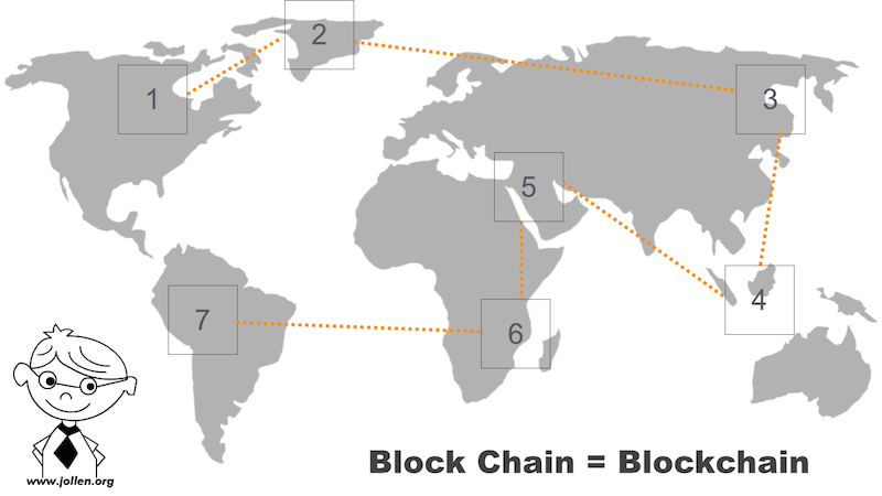
圖 2:Block 與 Chain
這些分散在世界各地的 Block,都會有一個編號,如圖 3。這個編號就是區塊產生的「順序」。
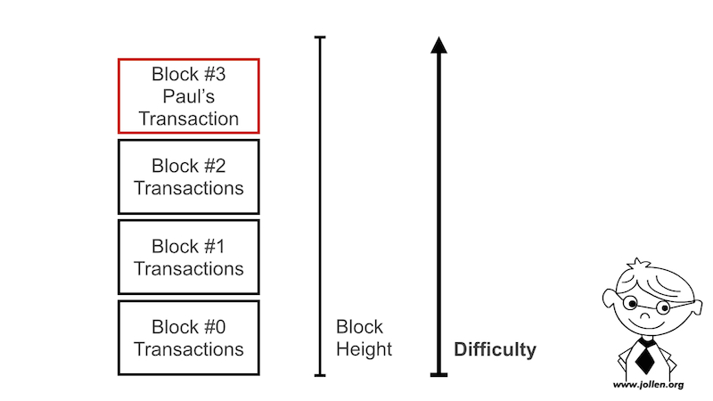
圖 3:Block #0
這其中,就一定會有編號為 0 的第一個區塊,這個區塊就稱之為 Genesis Block(創世區塊),學習如何建立 Genesis Block 就是 Blockchain 系統開發者的第 2 堂課。
而區塊的產生「方式」,則可以由 Blockchain 的系統開發者來設計。以 Nakamoto Blockchain 來說(Bitcoin 的 Blockchain 系統),區塊的產生過程,就稱為「挖礦」。
那 Merkle Tree 與 Blockchain 的關係倒底是什麼呢?將 Blockchain、Genesis block 與 Merkle tree 放在一起討論時,它們的關係就是圖 4。
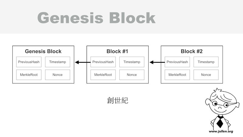
圖 4:Blockchain、Genesis block 與 Merkle tree
如果我發展一個叫做 Jollen's Blockchain 系統時,一個粗略的起步應該就是:
建立 Genesis block,genesis block 會有自已的一個 hash 值,這個值是經由 hash 演算法產生,因此也叫做 hash ID
利用演算法,經過一段困難的演算法運算,產生 Block #1
Block #1 也會有自已的 hash ID,同時, Block #1 要使用 PreviousHash 欄位,串接到前一個 Block,它的前一個 Block 就是 Genesis block(Block #0)
同理,產生 Block #2 與更多 Blocks,這些 block 之間都用 PreviousHash 欄位串接,這條鏈就是 Block chain
到這邊,還是很好奇 Merkle tree 的用途啊?回顧圖 4 發現,每個 Block 裡面都會有 Merkle Root 欄位,這個欄位就是一顆 Merkle tree。
區塊倒底能做什麼呢?每一個區塊,都能用來「記帳」,整個 Blockchain 串接起來就是一本完整的帳冊,所以說,Blockchain 也叫做 distributed ledger(分散式帳冊)。
更深入技術來看,區塊裡的 Merkle tree 就是負責記帳的欄位。
這幾天因為專案需要,開始將線上支付的金流平臺,從 Paypal 轉移到 Pay2go。在實作前端與後端的過程中,發現有一些應該要注意的事項。
由於 Pay2go 是以 Form Post(HTML5 的 <form></form>)的方式提交付款請求,所以必須使用 <input> 來紀錄交易參數,如圖一。

圖一:MPG API
一個稱為 CheckValue 的參數,編碼規則如下:
var data = 'HashKey=' + hashKey +
          '&Amt=' + amt +
          '&MerchantID=' + merchantID +
          '&MerchantOrderNo=' + merchantOrderNo +
          '&TimeStamp=' + timeStamp +
          '&Version=1.2' +
          '&HashIV=' + hashIV;
// 使用 SHA256 壓碼後轉大寫
var checkValue = sha256(data).toLocaleUpperCase();
將幾個主要的交易參數、 hashKey 與 hashIV 連接成 Query String 形式後,再用 SHA256 編碼。CheckCode 看起來是為了檢查交易參數的正確性。不過:
CheckCode 放在 Form 的欄位裡,有安全上的疑慮CheckCode,但 Pay2go 目前不支援這樣的做法另外,有些前端網頁,直接將 hashKey 與 hashIV 也紀錄在 Form 裡面,也是非常危險的做法。如圖二(為避免不必要的問題,僅做截圖,無註明出處)。

圖二:曝露在外的 hashKey 與 hashIV
類似的安全議題,可以在研發或工程階段,就進行嚴格檢視。不過,把交易機制、平台架構與 SDK 做到非常嚴謹,應該是金流平臺的基本責任。
一個安全且嚴謹的交易平臺,也要針對各種「使用不當」的案例,而造成的安全疑慮,進行完整測試。
NotifyURL 是 Pay2go 用來通知店家後台交易結果的 URL。Pay2go 在訂單完成交易後,會以 HTTP POST 方法,呼叫 NotifyURL。店家的後台則是要實作這個 API,並進行自已的訂單處理流程。
以下是一個 Pay2go 模擬交易,所回送的 POST 資料:
{ JSONData: '{"Status":"SUCCESS","Message":"\\u4ed8\\u6b3e\\u6210\\u529f","Result":"{\\"MerchantID\\":\\"31745140\\",\\"Amt\\":992,\\"TradeNo\\":\\"16033018180593725\\",\\"MerchantOrderNo\\":\\"14593335802368129\\",\\"RespondType\\":\\"JSON\\",\\"CheckCode\\":\\"4E2B2FB0A54CCFECE9616742FE9025EFBBE8FABBC6562268C11D39DFD6E03E9C\\",\\"IP\\":\\"36.231.213.27\\",\\"EscrowBank\\":\\"KGI\\",\\"PaymentType\\":\\"WEBATM\\",\\"PayTime\\":\\"2016-03-30 18:18:05\\",\\"PayerAccount5Code\\":\\"-\\",\\"PayBankCode\\":\\"-\\"}"}' }
這份資料會以 JSON 格式,經由 POST 方法,由 Pay2go 後台傳送到店家的 NotifyURL。將這筆資料的 JSONData 轉換為 JSON 物件:
var jsonData = JSON.parse(postData.JSONData); // postData 為上述回傳資料詳細的交易狀態,則是紀錄在 jsonData 的 Result 裡,再將這個欄位轉換為 JSON 物件:
var result = JSON.parse(jsonData.Result);終於得到以下內容(疑問:為什麼不直接回傳一個 Stringify 過的 JSON 物件就好?):
{ MerchantID: '31745140',
  Amt: 992,
  TradeNo: '16033018180593725',
  MerchantOrderNo: '14593335802368129',
  RespondType: 'JSON',
  CheckCode: '4E2B2FB0A54CCFECE9616742FE9025EFBBE8FABBC6562268C11D39DFD6E03E9C',
  IP: '36.231.213.27',
  EscrowBank: 'KGI',
  PaymentType: 'WEBATM',
  PayTime: '2016-03-30 18:18:05',
  PayerAccount5Code: '-',
  PayBankCode: '-' }
這個回傳結果也是頗耐人尋味:
CheckCode 放在這裡面,不但有安全上的疑慮,必要性也值得探討CheckCode 的目的,如果是為了 Pay2go 與店家,自驗證交易資料使用(沒有被竄改),或許可以在各自的後台運算即可,是否以明文傳送,或許有討論空間回傳的結果,在交易使用的 Form 裡面幾乎都可以取得。因此向店家發出一個「模擬交易成功」的 NotifyURL 並不是太困難。
NotifyURL 參數,避免用心人士,向店家發出「模擬交易成功」的通知。可以在 Pay2go 的管理介面設定 NotifyURL,減少 NotifyURL 曝露的機會。hashKey 與 hashIV。NotifyURL 可以考慮移除「自動出貨」、「自動付款銷核」等流程,取消部份自動化,改採手工銷核。NotifyURL 實作,可以考慮加入更嚴謹的檢查,例如查看 HTTP 的 Origin:,或是 Refer: 等檔頭。不過因為 HTTP headers 也是很容易變造,所以根本之道還是 Pay2go 的後台能強化相關機制。最後,展示如何用 curl 進行「模擬交易成功」。首先,在店家的 Form 裡面取得 MerchantID、CheckValue、MerchantOrderNo 與 Amt 四個參數。
接著,將以上參數帶入以下的內容模板:
{
"JSONData": "{\"Status\":\"SUCCESS\",\"Message\":\"\\u4ed8\\u6b3e\\u6210\\u529f\",\"Result\":\"{\\\"MerchantID\\\":\\\"31745140\\\",\\\"Amt\\\":992,\\\"TradeNo\\\":\\\"16033018180593725\\\",\\\"MerchantOrderNo\\\":\\\"14593258232469307\\\",\\\"RespondType\\\":\\\"JSON\\\",\\\"CheckCode\\\":\\\"4E2B2FB0A54CCFECE9616742FE9025EFBBE8FABBC6562268C11D39DFD6E03E9C\\\",\\\"IP\\\":\\\"36.231.213.27\\\",\\\"EscrowBank\\\":\\\"KGI\\\",\\\"PaymentType\\\":\\\"WEBATM\\\",\\\"PayTime\\\":\\\"2016-03-30 18:18:05\\\",\\\"PayerAccount5Code\\\":\\\"-\\\",\\\"PayBankCode\\\":\\\"-\\\"}\"}"
}
將上述內容儲存為 test.json。最後利用 curl 向店家的 NotifyURL 發出 POST 請求:
curl -X POST -d @test.json --header "Content-Type: application/json" http://localhost:80/pay2go/notify
從這個「模擬交易」的測試可以知道,把自已的 NotifyURL 藏好是一個很重要的工作。提供 REST API 來替代 Form Post 方式,可以消除主要的安全疑慮。
DLT 有一個更耳熟能詳的名字,叫做區塊鏈。簡單來說,根據 Wikipedia 上的定義 1,區塊鏈(Blockchain)就是一種 Distributed Ledger 的資料結構(Data Structure):
a Blockchain is only one type of data structure considered to be a distributed ledger.
也就是說,DLT 可以延用 Blockchain 資料結構設計,也可以根據應用的不同,設計全新的資料結構;無論是採用 Blockchain 資料結構,或是設計新的資料結構,目標都是提供一個分散式資料儲存系統(distributed data storage)。一個 DLT Platform 除了要具備一個安全可信任的 distributed data storage,還具備以下 2 個元素:
在 distributed data storage 網路上的電腦裝置,稱之為節點。由於 distributed data storage 需要考慮備援與錯誤修正的問題,因此會經一筆資料同步備援在多個節點上,這樣的技術就稱為 replication。當某一個節點上的該筆資料毀損時,扮演該筆資料備援角色的節點,就能協助該節點,回覆毀損的資料,這樣的技術就稱為 redundancy。
技術上,DLT 就是一個為 distributed data storage 提供 replication/redundancy 功能的通訊協定(Protocol)。這樣的 replication/redundancy 機制,就稱為 fault tolerance(容錯機制)。
DLT 與傳統資料庫系統,除了上述的差別外,另一個重要的區別是:交易。DLT 儲存的是交易(Transaction);而傳統資料庫儲存,則是儲存「資料」(Data)。
交易與資料的一個區別是,交易需要被「驗證」(validation);而資料卻是可以直接地,儲存進資料庫裡即可。交易會包含所要儲存的資料,因此,可以說交易是資料的「封裝」。
在軟體設計的領域裡,封裝有「打包」的意思;也就是說,這像是在寄掛號信,我先將文件(資料)放進信封打包好,再將郵件「提交」到郵局,最後由收件人簽收無誤後取出文件,再將文件歸檔(儲存)。
在一個 DLT Platofmr 裡,交易的驗證過程,需要決定該筆交易的接受者與簽收方式,這就開始涉及 Broadcast 與 Consensus 技術了。最終,這筆交易會被節點儲存,而儲存交易的地方就稱為 Block(區塊),而這些區塊將不只一個,而是一個 chain of blocks 的結構,這些串接在一起的 blocks 就稱為 blockchain。
DLT 是一個比 blockchains 更整體的研究主題,例如知名的 Hyperledger 就是一個 DLT 平台。Fault tolerance 與 transactions 則是 DLT 的核心骨幹。像是 PBFT(Practical Byzantine Fault Tolerance )就是一個知名的 fault tolerance 演算法,並且被 Hyperledger Fabric v0.6 所採用。
SBFP(Simplified Byzantine Fault Tolerance)也是一種 fault toerance,由 Hyperledger Fabric v.10 實作;SBFP 演算法延續 PBFP,目的是能支援更大規模(large scale)的 p2p 網路。
A declarative, efficient, and flexible JavaScript library for building user interfaces.
🖖 Vue.js is a progressive, incrementally-adoptable JavaScript framework for building UI on the web.
TypeScript is a superset of JavaScript that compiles to clean JavaScript output.
An Open Source Machine Learning Framework for Everyone
The Web framework for perfectionists with deadlines.
A PHP framework for web artisans
Bring data to life with SVG, Canvas and HTML. 📊📈🎉
JavaScript (JS) is a lightweight interpreted programming language with first-class functions.
Some thing interesting about web. New door for the world.
A server is a program made to process requests and deliver data to clients.
Machine learning is a way of modeling and interpreting data that allows a piece of software to respond intelligently.
Some thing interesting about visualization, use data art
Some thing interesting about game, make everyone happy.
We are working to build community through open source technology. NB: members must have two-factor auth.
Open source projects and samples from Microsoft.
Google ❤️ Open Source for everyone.
Alibaba Open Source for everyone
Data-Driven Documents codes.
China tencent open source team.

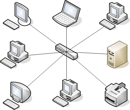


