This is a repo to compile all the 3d printer modifications and pcbs i have worked on with the voron discord community if you wanna help support me or buy a beer you can on patreon

BTC: 3AXN2g2H9qM47EwRjAcKVZ31yz7rMHWhGx
misc stuff
License: GNU General Public License v3.0
This is a repo to compile all the 3d printer modifications and pcbs i have worked on with the voron discord community if you wanna help support me or buy a beer you can on patreon
BTC: 3AXN2g2H9qM47EwRjAcKVZ31yz7rMHWhGx


Hi, do you have any plans to add selectable fan voltage in Toolhead PCB to stealthburner?
hi, i really like your work :)
i was trying to order you 2 piece pcb from PcbWay but they have big problems with the file. what software did you use to make the gerber's?
keep up the good work :))
Best Regards
Sebastian
Hi,
I just figured out that the 2 pices pcb have a different pin names for AUX connector.
1 picece: G S AG
2 pieces: G A1 AG
Now I'm using the 2 pieces and I have to connect the X Endstop Switch, but the readme tells I have to use G and S.
Would it be the same with A1 in place of S on the 2 pieces board?
Thanks!
Hi!
Can you please provide complete BOM list (with product numbers) so I know what to buy?
Thank you.
Thanks for adding the photo to the README specifying the modifications needed to make the Stealthburner toolhead PCB work with the Clockwork2 and LCO Breakout PCB. It appears that the wire ordering shown in the photo is incorrect. As my printer is not completed, I haven't tested the wiring described below. However, here's how I determined it should be wired:
First, let's establish the wiring for the original LDO Afterburner toolhead board so we know which motor wire colors correspond to A1, A2, B1, B2. Then we can translate these to the Stealthburner toolhead PCB.
The motor wire outputs are given in the P5 connector of the LDO Afterburner toolhead schematic
 P5: [ B2 B1 A2 A1 ]    LDO Afterburner Toolhead PCB

 (Pin 1 is the leftmost pin when looking at the connector with the keyways down on the connector side of the PCB.)
Next, the motor wire color order is given by examining the physical LDO-42STH20-1004ASH motor connector used for the Afterburner. It can also be seen in this picture.
So when the motor is connected to the LDO Afterburner toolhead PCB, we have:
 [ B2 B1 A2 A1 ]    LDO Afterburner toolhead PCB
 [ bk gn rd bu ]    LDO-42STH20-1004ASH motor

 (Pin 1 is the leftmost pin when looking at the connector with the keyways down on the connector side of the PCB.)
But the Stealthburner/Clockwork2 uses a different motor. So comparing the motor datasheets for the
42STH20-1004ASH and the 36STH20-1004AHG, we can map the wire colors:
 [ B2 B1 A2 A1 ]    LDO-42STH20-1004ASH motor
 [ bk gn rd bu ]    42STH20-1004ASH
 [ rd gn yl bu ]    36STH20-1004AHG
With that mapping, we can now look at the @hartk Toolhead PCB:
The Octopus motor_6 pinouts are
[ A1 A2 B2 B1]
The Octopus pinouts are documented here.
After installing the two-piece hartk Stealthburner PCB, I used a multimeter to check which pins at the Octpus motor_6 port (OCT_M6_x) matched which pins on the @hartk Stealthburner Toolhead PCB e-motor connector (SB_TH_PCB_x). I found:
     A1  ->  OCT_M6_1  ->  SB_TH_PCB_1
     A2  ->  OCT_M6_2  ->  SB_TH_PCB_3
     B2  ->  OCT_M6_3  ->  SB_TH_PCB_4
     B1  ->  OCT_M6_4  ->  SB_TH_PCB_2
Now we just have to translate the wire colors.
Using the mapping in step 3:
     A1  ->  OCT_M6_1  ->  SB_TH_PCB_1  -> bu
     A2  ->  OCT_M6_2  ->  SB_TH_PCB_3  -> yl
     B2  ->  OCT_M6_3  ->  SB_TH_PCB_4  -> rd
     B1  ->  OCT_M6_4  ->  SB_TH_PCB_2  -> gn
Sorting the table into toolhead connector order:
     A1  ->  OCT_M6_1  ->  SB_TH_PCB_1  -> bu
     B1  ->  OCT_M6_4  ->  SB_TH_PCB_2  -> gn
     A2  ->  OCT_M6_2  ->  SB_TH_PCB_3  -> yl
     B2  ->  OCT_M6_3  ->  SB_TH_PCB_4  -> rd
The table shows that the e-motor connector should be ordered:
 [ bu gn yl rd ]

 (Pin 1 is the leftmost pin when looking at the connector with the keyways down on the connector side of the PCB.)
But the photo in thie repository's README.md has
[ yl gn bu rd ]
It seems that the CAD files are still 2.4r1, not as stated: "Hartk mod update for 2.4r2 (VoronDesign/VoronUsers#638)"
Is there a forecast to when the 2.4r2 files uploaded?
In the diagram here:
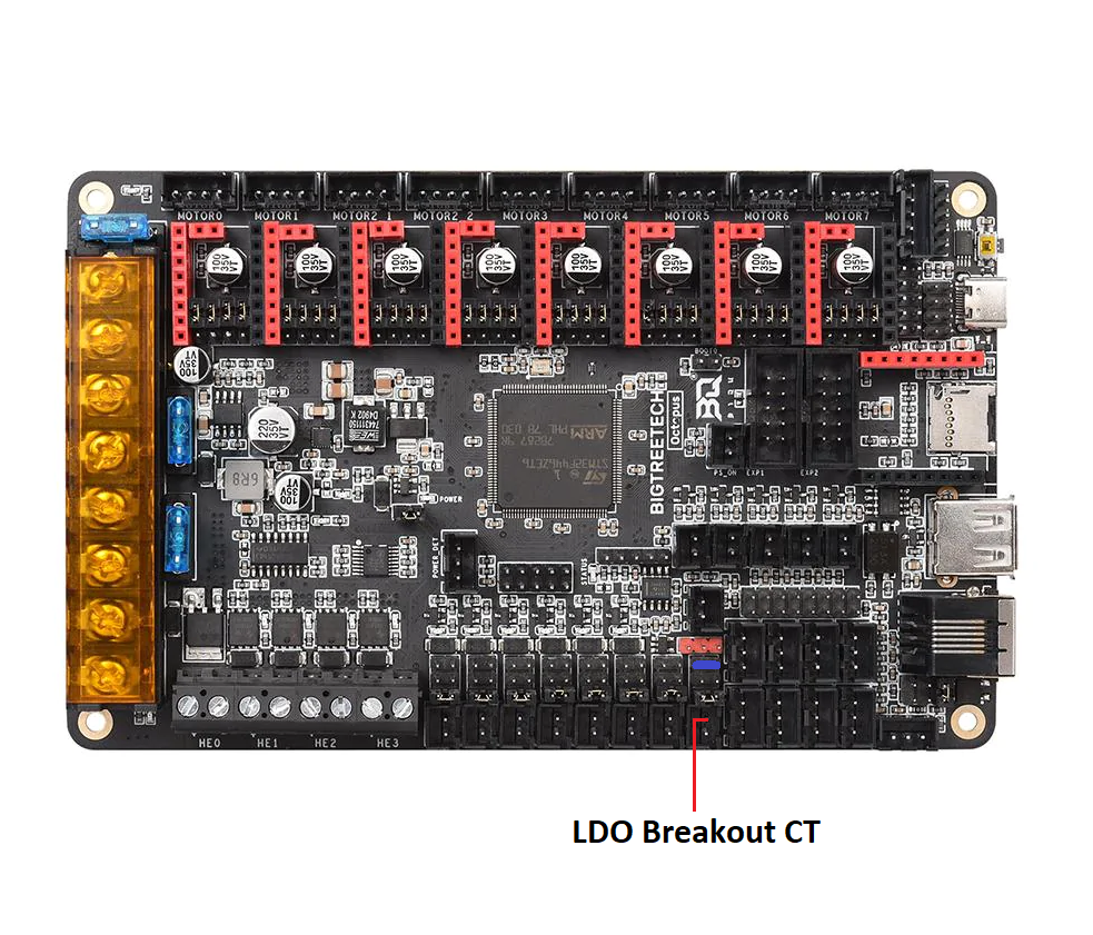
The picture suggests one should add the 5v jumper, but also clearly shows the 24v present too.
Having just blown an Octopus and Pi by following the instructions rather than reading the manuals - can I suggest we update the image to indicate that the 24v jumper needs to be removed?
The extruder pin order in Schematic_StealthburnerPCB.pdf does not reflect the silk screen and does not reflect actual traces either.
The Extruder pin order should be
S1A/S2A/S1B/S2B
while it currently reads: S1B/S1A/S2A/S2B
This is not the standard order for 4 pin stepper connectors.
Ideally, the traces should be updated to use the standard S1B/S1A/S2A/S2B that is normally used on 4 pin stepper connectors. From the gerber files, it does not look like there is anything preventing the correct pin order to be implemented.
The sleeves are nearly impossible to install. I think you intended them to be heat inserted but the instructions make no mention of it. I tried filing it to make it smoother but now the top sleeve is too loose. * purchased kit
Hey, did you by any chance make a version of the Y endstop relocation mod compatible with the Trident? I saw someone online mention that you have it in this repository, but the only one I could find is a variant for the V2.4 or for Trident but only with the pins mod.
Mellow's SB2040 uses XT30 plugs. As the XT30 plugs are slightly larger in size than the M12 holes, would it be possible to add a square slotted hole in the mount to allow the plugs to pass through more easily.
\Voron Mods/Voron 2-Trident/2.4/CW2_CAN_Umbilical/STLs/CW2/cw2_umbilical_m12.stl

your probe use 24v, new voron tap use 5v, please add 5v support
I'd think that adding a wire from the GND power return of the 4 CAN cable wires to the USB gnd at the CAN side would provide some safety since it would now be impossible to lose the ground connection without losing the data connections as long as the USB plug was inserted.
On the RPi side, if the 5v and 24v power supply grounds are connected together, the same should be true as the Pi USB ground should be connected to Earth and Power ground.
Better still would be to add suitable back to back zener diodes from each USB D line to ground. I don't know what the required breakdown voltage should be, but probably 6V would be close. I would think that both the EBB and RPi boards should have those diodes there already, if they were well designed!
Today I upgraded from an AfterBurner 4.0 PCB to the New 2-Piece PCB StealthBurner and upon powering on the System both Tool Head FANs spun up to ( I assume ) MAX thus needing some investigation what went wrong despite me carefully paying attention if anything in the 14-Pin Cable Connector had changed ( besides the CT to 5V change ).
After some probing I found out that the problem being tied to how I soldered the FAN wires to the Secondary PCB based on Silkscreen labeling:
Given the options of 24V, S, A1/A2, 5V & G - I established a connection via the 24V and G Pads but the latter does not connect to the respective PCF and HEF traces coming from the 14-Pin Connector on the Primary PCB. Instead I had to use the S Pad ( for both Fans ) which I find rather... Unusual to say the least.
Is this perhaps an Error in the Silk Screen?🤨
The store where I got my set from now populates the board with Dupont Headers which would have made it obvious but mine shipped bare ( and without the connectors ). Maybe I'm not the only one who got confused? 🤔
I have a rev 2 Stealthburner 2-piece PCB, and recently installed it as part of Stealthburner upgrade on my Voron. The extruder stepper didn't work when powered up. I suspected an issue with the stepper connections, and checked but it all seemed correct.
But now I notice that this is a known issue (#29) which has been closed. There is a note in the readme that the rev 4 PCB "stepper wiring has now been fixed", but no indication what the issue was or what was wrong with previous rev's.
Any chance the readme could be updated with a more prominent note to the issue with older rev PCB's ?
it doesn't seem like anybody actually solves these issues, but there is a serious conflict on the pinout_14_2 or whatever is named and the Octopus wiring diagram. the two are competently flipped upside down from each other in the 14-pin connector. which is correct?
Hi @hartk123! While assembling your V0.2 G2Z assembly I noticed that the changes in af036b8 moved the belt offset so it is no longer centered between the two z rails. I've attached a picture showing the change between the current and previous [a]_v0_g2_drive_mount_x1.stl (current on the left, previous on the right). Notice the height difference and position of the belt cutout on the newer part compared to the old.
If there's a CAD available I'm willing to attempt a fix, otherwise it's easy enough to print the older version.
Thanks for taking a look and publishing your designs for others to use.

printed and installed, was unable to get the side hole screwed in, tried multiple times. ended up shining a light and noticed it was partially blocked by the extrusion itself.
checking the cad also showed the hole is 6mm from the top and 10.5mm from the bottom.
my assumption is the hole was indexed on the outer face, which puts the hole in the center of that face, however that face includes ~4mm from the material that goes ontop of the extrusion.
its atleast more than strong with just the two top mounted screws


Would be nice if we could have a rear keystone skirt for V0.2 with two or three inserts for one or two USB ports.
The repository has the GPL 3.0 shown, but the source files for the PCBs don't seem to be shared anywhere. Please share source files, thanks.
Cant get access to the JST connectors for fans. No finger room. Pulled the plastic parts off the pins on the board trying to remove. Cant get back on with needle nose pliers. Magnetic probe didnt work on the first go. Just tried klicky probe but dont know gcode and ran in to a wall on the instructions as result of. Sadly I have to tear this all out now and go back to afterburner. This board is a good idea but the jst connectors with no finger room forcing a removal of the board just to get them back on each time I have to take the print head off is not something I want to sign up for.
The BOM for the GE5C Z joint calls for 4x M5x20, but these are two short. Without the belt and "M5x1mm spacer" in place it just about reach the T-nut, but with the washer it's just too short. M5x25 screws do the trick.
The BOM also doesn't mention the 4 extra M3x16 screws that replace the original ones for the belt clip (see arrow in image below), as those are too long.


Hello,
is there something strange with GND? My PCF shut down the Neopixels at startup.
(HARTK SB PCB)
On the Schematic_StealthburnerPCB.pdf, the pinout of the AUX connector is inversed compared to the PCB and wiring instructions.
Pin 1 should be GND.
Pïn 2 is correct.
Pin 3 should be AGND.
Thanks for your work ! :)
Good day!
After seeing a post on facebook about some issues about this board, I decided to give it a look and help out the community. As for my qualifications, I've designed the Carabiner Toolboard which is similar to the Doomboard in some areas.
But, that's not relevant, let me please point out a few issues with the current design that are literal potential fire-hazards that in the best case 'just' destroy the Doomboard, and in the worst case the mainboard of the printer.
They'll be listed from least severe to most severe.
First - The lower-left screw-hole. While not major, but the top 24V fill when combined with a washer could potentially cause the screw to carry 24V - this could short to the thermistorGnd. I'd recommend switching this over to a hole with a dedicated pad. While not fixing the issue with the washer it makes it more clear to people that there is no washer intended here.
Second - The HeaterGND trace. This is currently seemingly specced with 0.8mm. This means at an T_rise of 10° (10° over ambient temperature in the chamber) it could handle 2A. For a heater this is fairly low and considering that the Doomboard is inside a Voron (which are usually enclosed) and the extra enclosure will only trap heat inside even more - this will over time likely deteriorate the trace and will burn it out - leaving the board pretty much dead. As for this, I'd recommend increasing the width of the trace to at least 1.4mm (3A current capability with 10° T_rise).
Third - The screw-hole besides the 14-pin. This is what brought me here in the first place - due to not having a pad, the screw-head can very-likely scratch the coating of the HeaterGnd and ChamberThermistor. This could cause 24V to go to the thermistor and potentially cause major havoc there - depending on the board it might fry the MCU. As such I'd highly recommend switching this over to a padded hole - even though this will likely need massive trace re-routing.
Overall I'd recommend you to have another look at the traces - if e.g. the BAT-diode would be flipped 180° the routing from the top-left of the 14-pin would be much nicer and would make for a much cleaner route.
I don't wanna say this will burn your house down - but if everything goes wrong, it could burn down someones house. As such I strongly urge you to please fix those issues in a Rev 4.0 board as many Voron users seem to be using it, and having such potentially desastrous issues on a board with a sizeable userbase is not good for the whole 3dp community.
If you wanna chat about those things, please contact me in Discord, iKirin # 0001. I'll gladly help you to improve this board so we all can enjoy a better 3D-Printing space.
Best regards,
iKirin
PCB Hacker at Annex Engineering
Why did you use 24v on the filament sensor port when most of the filament sensors are between 3.3v and 5v?
hello do you plan to make something like Frame PCB for your mod FPC Toolhead PCB ??
https://raw.githubusercontent.com/timmit99/Voron-Hardware/V0-Umbilical/V0-Umbilical/Images/Frame_PCB.png
Slight issue with the Y Endstop relocation mod, the model is based on the 2.4r1 files and the Z chain mount holes are now different.
The 2.4r1 has two mounting holes for the Z chain mount, the 2.4r2 has one single hole in the middle.
Might be a good time to re-do this mod with the original 2.4r2 files, as the geometry on the parts have also slightly changed.
Hi
I used your link to create an order of https://github.com/hartk1213/MISC/tree/main/PCBs/Stealthburner_Toolhead_PCB
I've got a lot of electronics experience but I've never ordered PCBs (usually I just etch my own).
I got a response from PCBWay as follows:
Good day. Thanks for you PCB order#xxxxxxxxxxxx_Gerber_Stealthburner.
There is an engineering question in your Gerber File. As shown in the attached screenshot, there are 3 holes are overlopped and sizes are different. Which layer should we use? (drl or dril+1)
Please check and advise.
The lead time will be re-calculated after the EQ is solved.
Any chance you could provide some guidance?
Greetings,
Today I've finally managed to dedicate some time going after the cause of the KlipperScreen interference problem that I'm having every once in a while 😩
The issue has been plaguing me pretty much from Day 1 when I installed the Screen with the Afterburner / ClockWork 1 4.0 PCB already being present but for whatever reason at some point the problem lessened to be 99% solved - How? I don't know...
Come the StealthBurner / ClockWork 2 and I've upgraded to the Two Piece PCB - Bäm... Back to Interference whenever the Extruder Motor is engaged until they are turned off again.
YouTube Video demonstrating the issue when it REALLY messed with the system causing flickering of the screen, phantom keypresses that had the chance to pause or even emergency shutdown the system etc... Nowadays the screen remains readable but interaction with the screen is again practically impossible as touch inputs will be recognized at the wrong location.
Slightly annoyed I went and:
I did mod the PCB to remove the BAT85 Diode ( not necessary for the BTT Octopus V1.1 ) and bridged the gap but that's about it.
Other than the Screen issue the Printer is working without issues - Any Ideas what is going on? 🤨
Hi. Do you have the CAD for the CNLink threaded CW2 mount please? It doesn't appear to be included in the step file.
As the pcb gets both 24 and 5 volt, will there be a jumper field for the probe and the fans like in the AB ERCF toolhead pcb?
Only with the last few days did you update the wording in the readme to state that M3 plastic washers should be used. I purchased my parts prior to this new advisement and I am wondering just how vital it is to do this.
A declarative, efficient, and flexible JavaScript library for building user interfaces.
🖖 Vue.js is a progressive, incrementally-adoptable JavaScript framework for building UI on the web.
TypeScript is a superset of JavaScript that compiles to clean JavaScript output.
An Open Source Machine Learning Framework for Everyone
The Web framework for perfectionists with deadlines.
A PHP framework for web artisans
Bring data to life with SVG, Canvas and HTML. 📊📈🎉
JavaScript (JS) is a lightweight interpreted programming language with first-class functions.
Some thing interesting about web. New door for the world.
A server is a program made to process requests and deliver data to clients.
Machine learning is a way of modeling and interpreting data that allows a piece of software to respond intelligently.
Some thing interesting about visualization, use data art
Some thing interesting about game, make everyone happy.
We are working to build community through open source technology. NB: members must have two-factor auth.
Open source projects and samples from Microsoft.
Google ❤️ Open Source for everyone.
Alibaba Open Source for everyone
Data-Driven Documents codes.
China tencent open source team.
