Monialaprojekti PRO4TN004-3005
A simple Arduino and Raspberry Pi based access control system built for a course at Haaga-Helia University of Applied Sciences.
The goal of this project was to create a simple access control system between Arduino Uno and Raspberry Pi. The system consists of Arduino Uno, Raspberry Pi 3B+, 9-12V DC solenoid lock, 3x3 membrane keypad and 2x NRF24L01 radio transceiver modules. The lock is controlled by inputting a correct PIN code using the keypad connected to the Arduino. The Raspberry Pi acts as a backend for this system and it is used for storing and viewing the logs based on the solenoid lock activity.
- Juuso Haapaniemi - Project manager
- Konsta Toivonen - Tech lead
The first goal for our project was to test each individual component to see that they work and to get basic knowledge on how to use them. All of our code used for testing can be found from "tests" -folder in our project and by pressing the small triangles in this documentation.
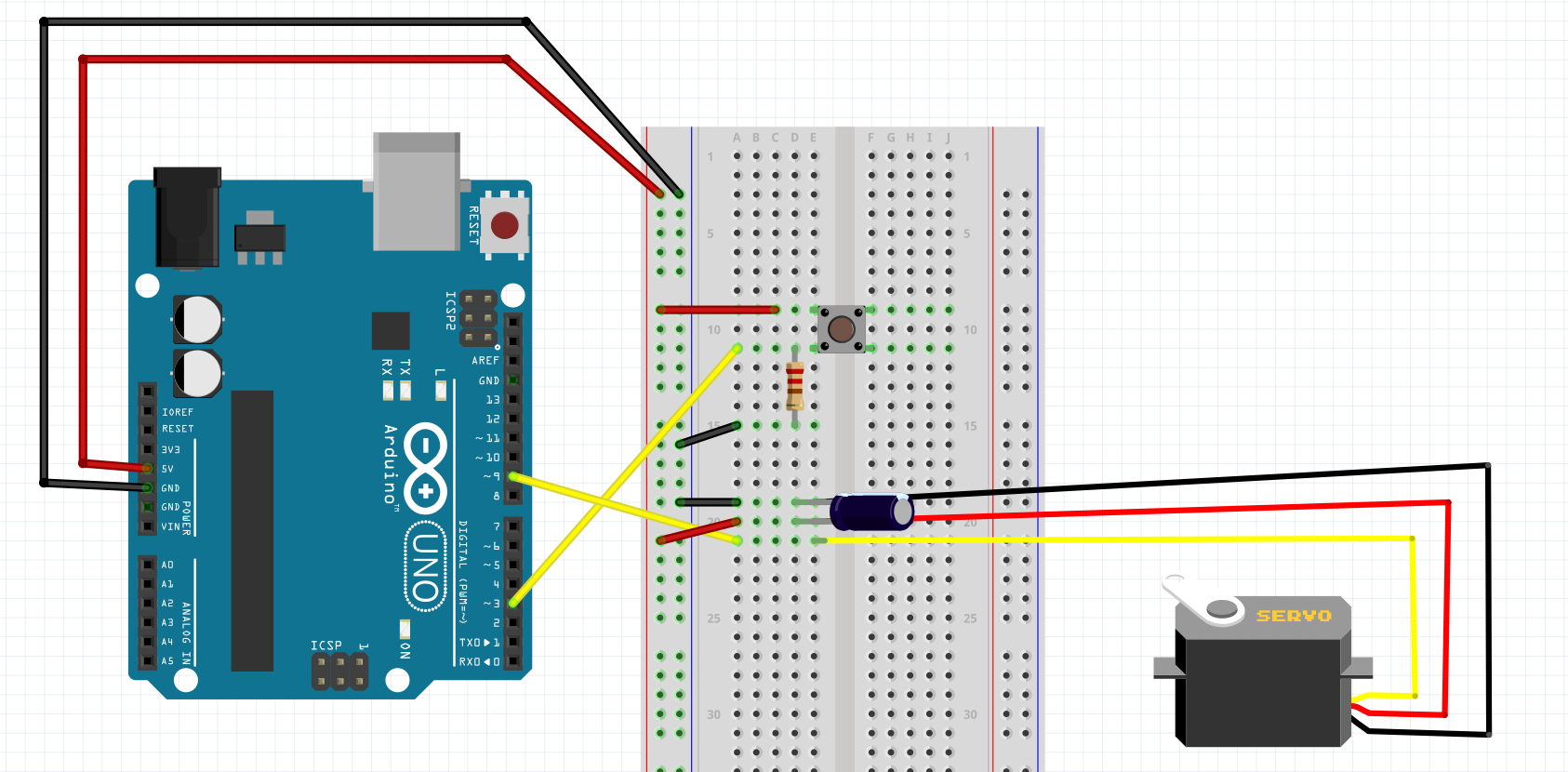
Testing the servo using a simple button switch connected to the Arduino breadboard.
nappimoottori.ino
#include <Servo.h>
Servo myServo;
int angle;
int switchState = 0;
int switchPin = 2;

void setup() {
myServo.attach(9);
Serial.begin(9600);
pinMode (switchPin, INPUT);
}

void loop() {
switchState = digitalRead(switchPin);
if (switchState == HIGH) {
  angle = 0;
} else {
  angle = 180;
}
myServo.write(angle);
delay(15);
}
Our original servo did not work as we expected. It did not move and only made a buzzing noise.
We changed the servo to another one, which worked, but later on we ended up using a solenoid lock. More on that later.
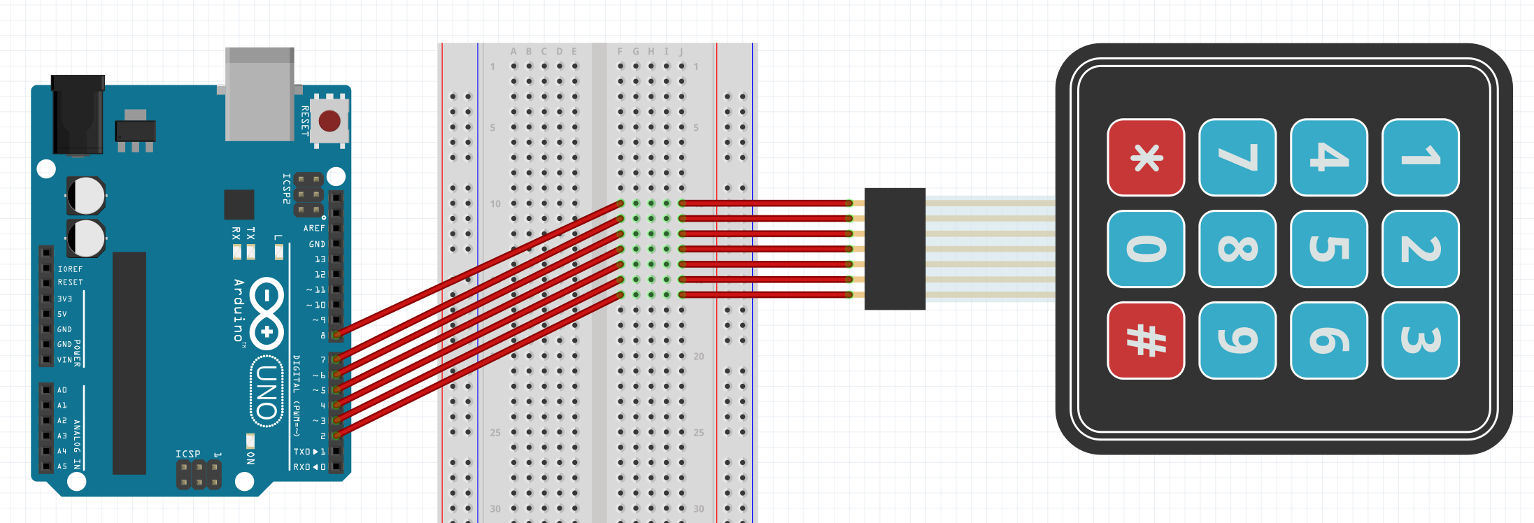
Next up: testing out our keypad.
keypad.ino
#include <Keypad.h>

const byte numRows = 4;
const byte numCols = 4;

char keymap[numRows][numCols] =
{
{'1', '2', '3', 'A'},
{'4', '5', '6', 'B'},
{'7', '8', '9', 'C'},
{'*', '0', '#', 'D'}
};

byte rowPins[numRows] = {9, 8, 7, 6};
byte colPins[numCols] = {5, 4, 3, 2};

Keypad myKeypad = Keypad(makeKeymap(keymap), rowPins, colPins, numRows, numCols);

void setup()
{
Serial.begin(9600);
}

void loop()
{
char keypressed = myKeypad.getKey();
if (keypressed != NO_KEY)
{
  Serial.println(keypressed);
}
}
In this example we used all keys available on the keypad. Later on we realized that our Arduino Uno did not have enough DigitalPins, so we ended up using only 3x3 keys. This will be demonstrated later on. Please note that we could not find a proper part for our schematic. We had to use a 3x4 keypad in the schematic instead of a 4x4. The wirings are still representative of the actual project.
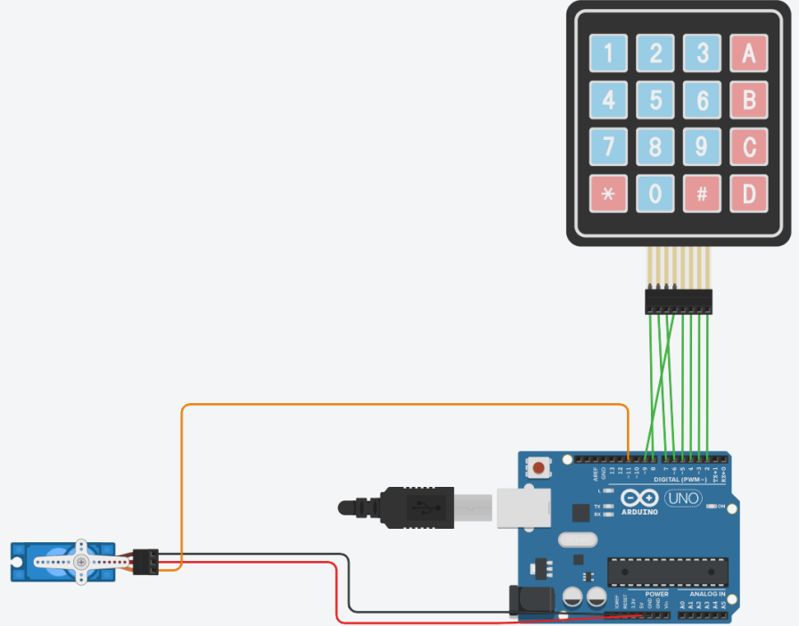
Moving the servo using our keypad. Created also our first iteration for a system using PIN code to unlock the door.
keypad_servo_test.ino
#include <Keypad.h>
#include <Servo.h>

Servo servo_Motor;
const char* password = "7856";
int position = 0;
const byte ROWS = 4;
const byte COLS = 4;
char keys[ROWS][COLS] = {
{'1', '2', '3', 'A'},
{'4', '5', '6', 'B'},
{'7', '8', '9', 'C'},
{'*', '0', '#', 'D'}
};

byte rowPins[ROWS] = { 9, 8, 7, 6 };
byte colPins[COLS] = { 5, 4, 3, 2 };
Keypad keypad = Keypad( makeKeymap(keys), rowPins, colPins, ROWS, COLS );

void setup() {
Serial.begin(9600);
servo_Motor.attach(11);
setLocked(true);
}
void loop() {
char key = keypad.getKey();

if (key != NO_KEY){
  Serial.println(key);
}

if (key == '*') {
    position = 0;
    setLocked(true);
}

if (key == password[position]) {
  position ++;
}

if (position == 4) {
  setLocked(false);
}
delay(100);
}

void setLocked(int locked) {
if (locked) {
  servo_Motor.write(0);
  Serial.println("Locking");
}
else {
  servo_Motor.write(90);
  Serial.println("Unlocking");
}
}
When the user enters the code 7856 on the keypad the servo moves 90°. The servo turns back 90° when * is pressed on the keypad.
Created a bootable MicroSD memorycard for Raspberry Pi 3B+ using Rufus and Raspbian Buster Lite.
We booted up the Pi and connected it to a monitor so we could enable SSH on it using the following command:
sudo raspi-config
In raspi-config we opened option 5: Interfacing Options > P2: SSH > Yes.
After enabling SSH on the Pi, we used the following command to create a new user:
sudo adduser konsta
and added the user to the groups "sudo" and "admin":
sudo adduser konsta sudo sudo adduser konsta admin
Then we locked user Pi using commands:
sudo usermod --lock Pi
We copied our SSH key to the Pi:
ssh-copy-id 192.168.1.180
Then we disabled password log in by modifying line "PasswordAuthentication yes" to "PasswordAuthentication no"
sudoedit /etc/ssh/sshd_config
Enabled firewall:
sudo apt update && sudo apt install ufw -y
sudo ufw allow 22/tcp
sudo ufw allow 80/tcp
sudo ufw allow 443/tcp
sudo ufw enable
Installed updates:
sudo apt upgrade -y
Installed needed packages:
sudo apt install python3 apache2 php libapache2-mod-php
Modified the default homepage of Apache2:
nano /var/www/html/index.html
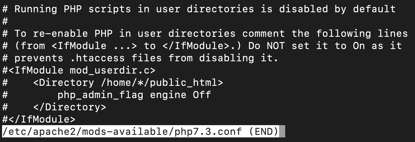
Allowed running PHP in user directories by commenting out necessary lines in /etc/apache2/mods-available/php7.0.conf:
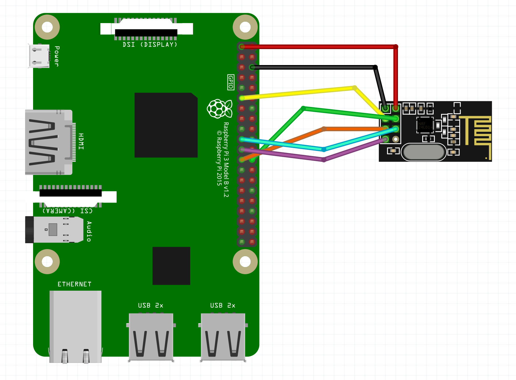
Testing the communication between Arduino and Raspberry PI using radio transceiver modules. The testing and actual finished project uses BLavery's Python2/3 lib_nrf24 library for NRF24L01+ Transceivers.
Link to BLavery's original lib_nrf24 library: https://github.com/BLavery/lib_nrf24/blob/master/lib_nrf24.py
The lib_nrf24.py we used has been modified with an addional fix line below. Adding this extra line fixed our transmissions not being received by Raspberry.
self.spidev.max_speed_hz=4000000
This extra line was added into lib_nrf24.py line 374.
self.spidev.open(0, csn_pin)
self.spidev.max_speed_hz=4000000
self.ce_pin = ce_pin
Code that was used to test sending data over to Raspberry.
radio.ino
#include <SPI.h>
#include <nRF24L01.h>
#include <RF24.h>

RF24 radio(7, 8); // CE, CSN
const byte address[6] = "00001";

void setup(void){
  Serial.begin(9600);
  radio.begin();
  radio.setPALevel(RF24_PA_MIN);
  radio.setChannel(0x76);
  radio.openWritingPipe(address);
  radio.enableDynamicPayloads();
  radio.powerUp();
  radio.stopListening();
}

void loop(void){
  Serial.println("Attempting to send data");
  const char text[] = "Hello World";
  radio.write(&text, sizeof(text));
  Serial.println("Sending message Hello World");
  delay(1000);
}
Early code that was used to test receiving data from Arduino.
ReceiveArduino.py
import RPi.GPIO as GPIO
from lib_nrf24 import NRF24
import time
import spidev

GPIO.setmode(GPIO.BCM)

pipes = [[0xE8, 0xE8, 0xF0, 0xF0, 0xE1], [0xF0, 0xF0, 0xF0, 0xF0, 0xE1]]

radio = NRF24(GPIO, spidev.SpiDev())
radio.begin(0, 17)

radio.setPayloadSize(32)
radio.setChannel(0x76)
radio.setDataRate(NRF24.BR_1MBPS)
radio.setPALevel(NRF24.PA_MIN)

radio.setAutoAck(True)
radio.enableDynamicPayloads()
radio.enableAckPayload()

radio.openReadingPipe(1, pipes[1])
radio.printDetails()
radio.startListening()

while(1):
    # ackPL = [1]
    while not radio.available(0):
        time.sleep(1 / 100)
    receivedMessage = []
    radio.read(receivedMessage, radio.getDynamicPayloadSize())
    print("Received: {}".format(receivedMessage))

    print("Translating the receivedMessage into unicode characters")
    string = ""
    for n in receivedMessage:
        # Decode into standard unicode set
        if (n >= 32 and n <= 126):
            string += chr(n)
    print("Out received message decodes to: {}".format(string))
During testing we were having some issues with some messages not being received by Raspberry. We later found out that by lowering the radio transceiver datarate with radio.setDataRate(RF24_250KBPS); to 250KBPS got us a much better success rate in sending the data.
After we finished testing out all of the individual components we can start combining them and the code used to test them.
This is an early test code from when the project was still using the rotating servo as a locking mechanism. There is no logging with the code yet.
accesscontrol.ino
#include <Servo.h>
#include <Keypad.h>
#include <SPI.h>
#include <RF24.h>

Servo servo_Motor;
const char* password = "2222";
int position = 0;
const byte ROWS = 4;
const byte COLS = 4;
RF24 radio(9, 10);

char keys[ROWS][COLS] = {
  {'1', '2', '3', 'A'},
  {'4', '5', '6', 'B'},
  {'7', '8', '9', 'C'},
  {'*', '0', '#', 'D'}
};

byte rowPins[ROWS] = {7, 6, 5, 4};
byte colPins[COLS] = {3, 2, 1, 0};
Keypad keypad = Keypad( makeKeymap(keys), rowPins, colPins, ROWS, COLS );


void setup() {
  servo_Motor.attach(8);
  Serial.begin(9600);
  setLocked(true);

  radio.begin();
  radio.setPALevel(RF24_PA_MAX);
  radio.setChannel(0x74);
  radio.openWritingPipe(0xF0f0f0f0E1LL);
  radio.enableDynamicPayloads();
  radio.powerUp();

}

void loop() {
  char key = keypad.getKey();

  if (key != NO_KEY){
    Serial.println(key);
  }

  if (key == '*') {
      position = 0;
      setLocked(true);
      const char lockedmessage[] = "Locked";
      radio.write(&lockedmessage, sizeof(lockedmessage));
  }

  if (key == password[position]) {
    position ++;
  }

  if (position == 4) {
    setLocked(false);
    const char unlockedmessage[] = "Unlocked";
    radio.write(&unlockedmessage, sizeof(unlockedmessage));
  }
  delay(100);
}

void setLocked(int locked) {
  if (locked) {
    servo_Motor.write(0);
    Serial.println("Locking");
  }
  else {
    servo_Motor.write(90);
    Serial.println("Unlocking");
  }
}
Our final, modified version of ReceiveArduino.py
import RPi.GPIO as GPIO
from lib_nrf24 import NRF24
import time
import spidev
import datetime

GPIO.setmode(GPIO.BCM)

pipes = [[0xE8, 0xE8, 0xF0, 0xF0, 0xE1], [0xF0, 0xF0, 0xF0, 0xF0, 0xE1]]

radio = NRF24(GPIO, spidev.SpiDev())
radio.begin(0, 26)

radio.setPayloadSize(32)
radio.setChannel(0x74)
radio.setDataRate(NRF24.BR_250KBPS)
radio.setPALevel(NRF24.PA_MIN)

radio.setAutoAck(True)
radio.enableDynamicPayloads()
radio.enableAckPayload()

radio.openReadingPipe(1, pipes[1])
radio.printDetails()
radio.startListening()

while True:
    ackPL = [1]
    while not radio.available(0):
        time.sleep(0.01)

    receivedMessage = []
    radio.read(receivedMessage, radio.getDynamicPayloadSize())
    print("Received: {}".format(receivedMessage))

    print("Translating the receivedMessage into unicode characters")
    string = ""
    for n in receivedMessage:
        if (n >= 32 and n <= 126):
            string += chr(n)
    print("Our received message decodes to: {}".format(string))
    radio.writeAckPayload(1, ackPL, len (ackPL))
    print("Loaded payload reply of {}".format(ackPL))

    now = datetime.datetime.now()
    f= open("logs.txt", "a+")
    f.write(now.strftime("%Y-%b-%d %H:%M")+" "+"{}".format(string)+"\n")
    f.close()
This code is ran on the Raspberry Pi and it is used to listen for the "Unlocked" message from Arduino. Once this message is received, it is added into 'logs.txt' with the time and date. At this point Raspberry then sends an acknowledgement payload back to Arduino to confirm that the message has been received. PHP and Apache are then used to read and display the contents of the 'logs.txt' by creating a static website.

index.html used to display logs
  <!DOCTYPE html>
<html>
<head>
  <meta charset="UTF-8">
  <title>
      Access log
  </title>
</head>
<body>
	<?php
		$file = file_get_contents('/home/konsta/monproj/logs.txt', true);
	echo nl2br ($file);
	?>
</body>
</html>
Final version of accesscontrol.ino
#include <Keypad.h>
#include <SPI.h>
#include <RF24.h>

const byte ROWS = 3;
const byte COLS = 3;

int RelayControlPin = 2;

String Password = "1234";
String tempPassword = "";
int i = 0;

RF24 radio(9, 10);

char keys[ROWS][COLS] = {
{'1', '2', '3'},
{'4', '5', '6'},
{'7', '8', '9'},
};

byte rowPins[ROWS] = {8, 7, 6};
byte colPins[COLS] = {5, 4, 3};
Keypad keypad = Keypad( makeKeymap(keys), rowPins, colPins, ROWS, COLS );

void setup() {
Serial.begin(9600);
pinMode(RelayControlPin, OUTPUT);
setLocked(true);

radio.begin();
radio.setPALevel(RF24_PA_MIN);
radio.setDataRate(RF24_250KBPS);
radio.setChannel(0x74);
radio.openWritingPipe(0xF0f0f0f0E1LL);
radio.enableDynamicPayloads();
radio.powerUp();
}

void loop() {
A:
i = 0;
tempPassword = "";
char key = keypad.getKey();

  if (key != NO_KEY) {
  Serial.println(key);
}

while (i < 4) {
char key = keypad.getKey();
if (key != NO_KEY){

  Serial.println(key);
  tempPassword += key;
  i++;

  if(tempPassword.startsWith("1",0)){
    } else if (tempPassword.startsWith("2",1)){
     } else if (tempPassword.startsWith("3",2)){
       } else if (tempPassword.startsWith("4",3)){
          } else {
              goto A;
                 }
}}
if (Password == tempPassword){
  setLocked(false);
  delay(5000);
  setLocked(true);
  goto A;
} else {
  goto A;
}
delay(100);
}

void setLocked(int locked) {
if (locked) {
  digitalWrite(RelayControlPin, LOW);
  Serial.println("Locking");
}
else {
  digitalWrite(RelayControlPin, HIGH);
  Serial.println("Unlocking");
  const char unlockedmessage[] = "Unlocked";
  radio.write(&unlockedmessage, sizeof(unlockedmessage));
}
}
This code checks the input PIN code and unlocks the solenoid lock once the correct code has been submitted. If the PIN code input is wrong, the code is "reset" and the PIN code input buffer is cleared. Once the lock is powered on to unlock it, an "Unlocked" message will be sent to Raspberry via the radio transceiver connected to Arduino. The lock is then automatically locked after 5 seconds by powering it down.
Here is the schematic of the final product.
We did not have a picture of a 12v battery pack for the schematic, so the picture has a 9v battery pack instead.


