The line following robot is one of the autonomous robots. That detects and follows a line drawn on the area. The line is indicated by a black line on a white surface or white line on a black surface. This robot must be sensed the color of the line. This application depends upon the sensors. Here we are using twenty IR sensors. The IR sensor used for path detection and Sharp sensor used for obstacle detection. These sensors mounted at the front end of the robot. The microcontroller is an intelligent device that controls the whole circuit.

The original objective of this robot was to take it to competitions where it would race against other robots, so my design always focused in achieving the highest speed while conforming to the rules of the competitions. Nonethless, every or almost every aspect of this robot can be modified to adjust for the needs, skills or budget of the maker.
Quala PID Pathfinder robot programmed by CodeVision AVR with C programming language which implemented and defined both PID and PWM methods for controlling the robot.
- Library: Defined all driver files and pin configuration so every other file can use this library for accessing to whole system parameters.
- Path Finding: These files contain two methods for following the line or avoid and pass the obstacle.
- Sensor: All those functionalities need to read the sensors values, find the line, detect the color of the line and provide data for controllers with IR sensors happen here.
- Move: Define all type of movement with two wheels and choose which controller should use for controlling motors driver.
- Controller: The methods implemented in these files which set motors speed depending on which controller was chosen manually. The PID controller uses the dynamic parameters to calculate the best speed for motors. There is a switch on board that you can change the controller between PID and PWM.
PID Control stands for Proportional-Integral-Derivative feedback control and corresponds to one of the most commonly used controllers used in industry. It's success is based on its capacity to efficiently and robustly control a variety of processes and dynamic systems, while having an extremely simple structure and intuitive tuning procedures. Although not comparable in performance with modern control strategies, it is still the best starting point when one has to start designing the autopilot for an unmanned aircraft. In fact, most existing attitude control functionalities found in commercial autopilots or open-source developments, rely on some sort of PID Controls. The structure of the PID controller is shown in below:

The PID Controller consists of the additive action of the Proportional, the Integral and the Derivative component. Not all of them have to be present, therefore we also often employ P-controllers, PI-controllers or PD-controllers. For the remaining of this text, we will describe the PID controller, while any other version can be derived by eliminating the relevant components.
The PID controller bases its functionality on the computation of the "tracking error" e and its three gains KP, KI, KD. In their combination, they lead to the control action u, as shown in the following expression:

The proportional term corresponds to the first term of the expression on the right side, the integral action to the second, and the derivative to the last one. Each of these terms plays specific roles in order to shape the transient and steady-state response of the closed-loop system. More specifically:
-
Proportional Action: The P-action is the component mostly relevant with the dominant response of the system. Increasing the P gain KP typically leads to shorter rise times, but also larger overshoots. Although it can decrease the setling time of the system, it can also lead to highly osciallatory or unstable behavior.
-
Integral Action: The integral action is typically employed to optimize the steady-state response of the system and shape its dynamic behavior. Essentially, it brings memory to the system. Increasing the I gain KI, leads to reduction of the steady-state error (often elimination) but also more and larger oscillations.
-
Derivative Action: The derivative action responds to the rate of change of the error signal and is mostly relevant with shaping the damping behavior of the closed-loop system. In that sense, increasing the D gain KD, typically leads to smaller overshoot and a better damped behavior, but also to larger steady-state errors.
-
Collective Action: As understood from this brief overview of the role of each action of the PID components, one cannot independently tune the three different gains. In fact, each one of them aims to offer a desired response characteristic (e.g. faster respone, damped and smooth oscillations, near-zero steady-state error) but at the same has a negative effect which has to be compensated by re-tuning another gain. Therefore, PID tuning is a highly coupled and iterative procedure.
A pathfinder robot with feedback from sensors and using PID controller for modifying the angle of robot's head with an Integrated mechanical design based on an AVR microcontroller. Without feedback, the robot is limited to using timing to determine if it's gone far enough, turned enough, or is going fast enough. And for mechanisms, without feedback, it's almost impossible to get arms at the right angle, elevators at the right height, or shooters to the right speed. There are a number of ways of getting these mechanisms to operate in a predictable way. The most common is using PID (Proportional, Integral, and Differential) control. The basic idea is that you have a sensor like an infrared or encoder that can measure the variable you're trying to control with a motor.
The concept of working of line follower is related to light. We use here the behavior of light at the black and white surface. When light fall on a white surface it is almost full reflected and in case of black surface light is completely absorbed. This behavior of light is used in building a line follower robot.
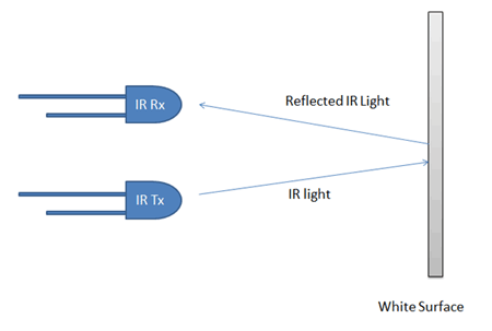
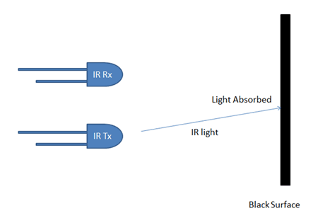
In this line follower robot we have used IR Transmitters and receivers also called photodiodes. They are used to send and receive infrared light. When infrared rays fall on the white surface, it’s reflected back and caught by receiver sensor. When IR light falls on a black surface, light is absorbed and no rays are reflected back, thus photodiodes do not receive any light or rays. Here in this robot when the sensor senses a white surface then buffer gets High as input and when the senses black line buffer gets Low as input.
AT90CAN128 8-bit AVR Microcontrollers is used for controlling whole the process of line follower robot. The outputs of comparators are connected to digital pins. AT90CAN128 read these signals and send commands to the driver circuit to drive the line follower. Driver section consists of two motor drivers and two DC motors. The motor driver is used for driving motors because AT90CAN128 does not supply enough voltage and current to the motor. So we added a motor driver circuit to get enough voltage and current for the motor. The microcontroller sends commands to this motor driver and then it drives motors.
| Unit | Description |
|---|---|
| Vision | IR sensors x20 |
| Motor Driver | L6203 x2 |
| Sensors Buffer | 74HCT244 x3 |
| Speed Controller | Manual - PWM/PID |
| Speed Boost | Auto |
| Distance Measuring | Sharp inferared sensor x3 |
| Sensor monitor | Led array |
| Parameters monitor | 16*2 Lcd |
| Programmer | AVR ISP MKII programmer |

| Unit | Description |
|---|---|
| Microcontroller | Atmel AT90CAN128 - 8-bit AVR Microcontrollers |
| Clock frequency | 12.000000 MHz |

Atmel AT90CAN128 has seven different ports.
| Connection | Pin |
|---|---|
| Sensor 16 | PINA.7 |
| Sensor 17 | PINA.6 |
| Sensor 18 | PINA.5 |
| Sensor 19 | PINA.4 |
| Sensor 20 | PINA.3 |
| Sensor 21 | PINA.2 |
| Sensor 22 | PINA.1 |
| Sensor 23 | PINA.0 |
| Connection | Pin |
|---|---|
| Motor1 Input 1 | PORTB.2 |
| Motor1 Input 2 | PORTB.0 |
| Motor2 Input 1 | PORTB.3 |
| Motor2 Input 2 | PORTB.4 |
| PID/PWM Switch | PINB.7 |
| Connection | Pin |
|---|---|
| Sensor 8 | PINC.0 |
| Sensor 9 | PINC.1 |
| Sensor 10 | PINC.2 |
| Sensor 11 | PINC.3 |
| Sensor 12 | PINC.4 |
| Sensor 13 | PINC.5 |
| Sensor 14 | PINC.6 |
| Sensor 15 | PINC.7 |
| Connection | Pin |
|---|---|
| Sensor 1 | PIND.6 |
| Sensor 2 | PIND.5 |
| Sensor 3 | PIND.4 |
| Sensor 4 | PIND.3 |
| Sensor 5 | PIND.2 |
| Sensor 6 | PIND.1 |
| Sensor 7 | PIND.0 |
| Connection | Pin |
|---|---|
| Speed booster relay | PORTE.2 |
| Connection | Pin |
|---|---|
| Sensor 24 | PINF.7 |
| Color sensor 1 | PINF.5 |
| Color sensor 2 | PINF.6 |
| Color sensor 3 | PINF.3 |
| Color sensor 4 | PINF.4 |
| Sharp sensor 1 | PINF.1 |
| Sharp sensor 2 | PINF.0 |
| Sharp sensor 3 | PINF.2 |
| Connection | Pin |
|---|---|
| Motor 1 PWM | OCR1B |
| Motor 2 PWM | OCR1A |
