Readout of Nefit/Buderus (Logamatic) EMS (=Energy Management System) interface Protocol by Arduino and transfer of data via HTTP GET requests to Domoticz home automation software (or to other systems).
There are also other names for 'EMS' or additions to EMS called EMS+, EMS2, Heatronic and Heatronic 3 but for most of those you need to do additional reverse engineering.
Although the code in this repository works fine for the most part, I suggest you have a look at the ESP code from Proddy. It has support for lots of boilers and thermostats out of the box, it's well maintained and features are added all the time.
I have written a plugin for Domoticz and EMS-ESP supports Home Assistant natively.
I'm also transferring most documentation to my dedicated wiki repository EMS-Wiki.
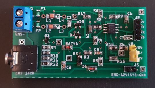
You can purchase a complete and tested interface board here.
Readout the Nefit/Buderus EMS interface of a Nefit Trendline gas boiler (gas condensing central heating boiler).
Transfer of data via ethernet to Domoticz home automation software.
The main sketch reads the EMS interface data and depending on the format decodes the data and puts it in variables.
You can then send the values via HTTP GET requests to Domoticz or do whatever you want with it.
Usage is not limited to Domoticz, you can extract the decoding part for other purposes.
There are also a few other sketches here to help you read and write to the EMS bus.
Furthermore there are some schematics here to help you build the converter circuit.
(Or buy a complete converter board here.)
Reading the EMS bus:
Should support all boilers using the EMS databus.
This includes most Bosch boiler brands like Nefit, Buderus, Worcester, and some Junkers. But also f.i. Sieger.
Datagrams containing status updates are periodically sent out by the boiler with source ID 0x08.
You only need to listen in. No data requests are needed for most boilers (But some only send the status automatically at boot).
However, several types of data are only send when the specific device on the bus is polled. For this you need to write to the bus.
Writing to the EMS bus: To change the temperature and other settings you need to write to the thermostat on the bus. This needs to be a EMS thermostat. Depending on the thermostat on your wall you need to send specific commands. Most of these are already reverse-engineered. Some are not. Below the list of thermostats which should work fine.
This list below is incomplete and no longer maintained. Check the full compatibility list here.
- Nefit 9000i
- Nefit TopLine
- Nefit TrendLine
- Nefit ProLine (only the non-NxT!)
- Nefit SmartLine
- Nefit BaseLine
- Bosch Compact
- Nefit EcomLine Elite (Just the Elite, older sub types often have the old iRT bus!)
- Sieger BK 15
The following boilers have no EMS bus and are thus not supported:
- Older Nefit EcomLine models like the VR24V, HR(C), Economy, HRC23VT (iRT protocol).
- Nefit ProLine NxT (OpenTherm protocol)
- Bosch HRC / HRC Top / HRS Top
- Bosch HRCII / HRSII
- Nefit Turbo
- Bosch Condens 3000W / 6000W
For the most specific info have a look at the EMS thermostat documentation page.
Short info:
EMS bus thermostats: RC20 (source ID 0x17), likely also RC30 and RC35 (both ID 0x10).
Depending on under which brand name these thermostats are sold they might have a different type name.
Some of the thermostats below are multi-protocol!
This means that although the thermostat will support the EMS protocol, they also support the older iRT protocol.
So if you have an old non-ems boiler like the Nefit Ecomline, you cannot use the code and the schematic in this repository.
| EMS code | Buderus type | Nefit type | Image |
|---|---|---|---|
| 0x17 | RC10? | Moduline 100 | 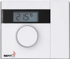 |
| 0x17 | RC20 | Moduline 200 | 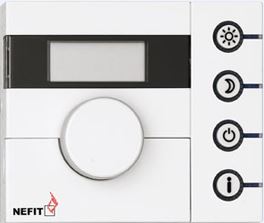 |
| 0x10/0x17 | RC30 | Moduline 300 | 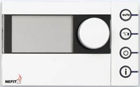 |
| 0x10 | RC35 | Moduline 400 | |
The RC30 is equal to the Nefit Moduline 300 and the RC35 is equal to the Moduline 400.
The RC20 is likely equal to the Nefit Moduleline 200.
Although the hardware is identical (if you open up a ModuLine 400 it says 'RC35' on the PCB), the firmware may be a bit different. It appears there are slight differences in frametypes. However, as more people are using theses sketches this will be resolved over time.
Furthermore in principle all EMS bus thermostats can be supported. So this also includes the Nefit Easy and the new line of ModuLine series 1000, 2000, 3000 etc. For a new thermostat you need to log the data on the bus when you set the temperature on the thermostat and go through the log to find the correct messages.
If you have a newer Nefit/Bosch/Buderus EMS thermostat and you would like to help I can give a hand. You can contact me via the Domoticz forum.
Non-compatible thermostats
| Buderus type | Nefit type | Image |
|---|---|---|
| iRT30 | ModuLine 30 | 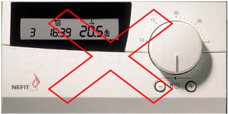 |
If you have an older thermostat looking like the one above, your boiler is NOT compatible with the EMS bus.
If your thermostat does not work, and you really want to change the temperature you might want to buy a supported model.
This Github page of Danidata has a very similar approach that works with the RC35.
You do NOT need to have an EMS compatible thermostat or a thermostat on the bus at all if you only want to read out the common status messages from the boiler!
Status updates regarding many parameters of the boiler are sent to the bus every 10 seconds.
I f.i. have an on/off thermostat zone control. So I do not have a Nefit thermostat at all. By connecting the EMS bus circuit to the service jack, I can still capture those status updates.
It is only if you want to read or write thermostat settings you need an EMS bus thermostat.
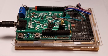
- EMS interface circuit (See Documentation or PBC-files folder).
- Arduino Mega 2560 Rev3 + Arduino Ethernet Shield with Wiznet w5100
- Raspberry Pi, PC or other device running Domoticz
The EMS bus interface can be converted to TTL level by means of a simple circuit. The TTL-converted signal can then be connected to one of the the Arduino UARTs. See the Documentation folder.
The sketches here use the Arduino Mega 2560 and the Wiznet 5100 ethernet shield. You can also use another Arduino like the Uno but that one only has one hardware serial port.
Serial1 is used for the EMS module. Serial(0) is used to debug the output to PC. EMS serial works with 9700 Baudrate and 8N1. You need a modified Serial library for the Arduino. It's included in the project.
The modified Serial library and thus the entire sketch will only work on Arduino (compatible) boards that have an Atmel AVR (ATmega) microcontroller on board like the Uno and Mega. ATSAMxx (ARM) type Arduino's are not supported. Neither are the ESP8266, ESP32 etc.
For the ESP8266 'Proddy' has written fully working code: https://github.com/proddy/EMS-ESP-Boiler
Arduino Mega pinout:
- Serial on pins 0 (RX) and 1 (TX),
- Serial1 on pins 19 (RX) and 18 (TX),
- Serial2 on pins 17 (RX) and 16 (TX),
- Serial3 on pins 15 (RX) and 14 (TX). You can choose any of the Serial ports on the Mega, the current sketch uses Serial1 but you can change that.
Arduino non-Mega: You cannot use Serial1, so you need to use Serial(0), which does not allow for combined debugging via serial.
It should be noted that the reverse-engineering of the EMS bus protocol was a major effort that involved many people. Most of it all started a few years ago on the mikrocontroller.net forum. Below two topics that hold all the original information:
http://www.mikrocontroller.net/topic/309075
http://www.mikrocontroller.net/topic/141831
At a later stage all information got nicely bundled at:
https://emswiki.thefischer.net/doku.php?id=start
In the end I combined code acquired from 'Jvdmeer' from the Nodo forum with methods to interface with Domoticz and published it here with lots of additional documentation for all to use.
That is on my list (maybe). For now it works exactly like my other Github project 'Vbus-Arduino-Domoticz'.
If you use a Mega, this is very easy to accomplish. Just check f.i. 'this website'. It will not work easily with an Uno, because you would need to use the software serial for reading the bus, this would also need modification to its library. But a Mega 2560 Rev3 is only a few Euro/Dollar on Ebay or Aliexpress anyway.
Sketch is based on the EMS sketches from 'Jvdmeer' from the Nodo forum.
The MIT License. This means that you can do whatever you want with my code! No need to ask me. It is always nice however to publish your version to Github to help others.
'Worcester, Bosch Group', 'Buderus' and 'Nefit' are brands of Bosch Thermotechnology.
All other trademarks are the property of their respective owners.


