Software developed for the remote control and monitoring of a laser at the Diamond Light Source I14 instrument.
The following documentation is designed as a guide to simplify the processes of preparing the hardware and installing this software, as well as extending its functionality and applying it to other components or instruments.
At the core of this "system" lies a Raspberry Pi, used as a server running a python script which allows it to process text-based commands that it receives over network. A Coherent Laser is connected to the Raspberry Pi via a USB-to-Serial interface, enabling the Pi to send commands to the laser and monitor its status. An Arduino board is also connected to the Raspberry Pi via a USB-to-Serial as well as a GPIO interface, and is mainly responsible for real-time generation of waveforms that are used to modulate the laser via a Digital-to-Analog converter (DAC). Additionally, a camera can also be connected to the Arduino, which can synchronise the camera's shutter with the modulation of the laser.
A diagram that illustrates this setup can be seen below. It was created using draw.io, and the source can be downloaded here.

The most noteworthy and desirable features of this project can be summarised as follows:
- Remote control of laser over LAN
- Remote monitoring of laser and safety interlock status over LAN
- High-precision control of laser output intensity
- Modulation of laser beam with pre-set waveforms of customisable period length and inter-cycle delay:
- Sine wave, triangle wave, sawtooth wave: cycle period between 1 millisecond and 1 second
- Square wave, pulse wave: cycle period between 1 millisecond and 1 hour
- Synchronisation of laser with connected camera:
- "gated mode": laser is turned on only when camera is exposing
- "master mode": camera exposure triggered when laser intensity reaches a customisable threshold
- Robust and extensible error handling
- Modular, well-documented code for easy customisation
The following section documents the steps required to correctly set up the hardware. It describes the setup of the operating system on the Raspberry Pi, as well as the required wiring between the Raspberry Pi, Arduino, DAC, laser and camera.
The Raspberry Pi used in this project is the Raspberry Pi 3 B+ (upgraded from the Raspberry Pi B Rev 2.0 on which development took place), chosen due to the following features:
- 1.4GHz processor (upgraded from 700MHz)
- 1GB SDRAM (upgraded from 512MB)
- 40 GPIO pins (upgraded from 26)
- Gigabit Ethernet
- MicroSD port
- PoE support
According to our specification, the Raspberry Pi needs to be set up so that it can do the following:
- run a headless Linux OS
- securely connect to a LAN
- communicate with other devices on the LAN via SSH
- communicate with laser via Serial-over-USB
- communicate with Arduino via Serial-over-USB and GPIO
- start Python server at boot and ensure it restarts on exit
The operating system chosen for this project was Raspbian Stretch Lite, an OS based on Debian Stretch with no desktop interface, chosen for its minimal footprint and high compatibility with Raspberry Pi. The required image was downloaded from the official mirror, and written to a 16GB microSD card according to the installation instructions.
As the Pi is being used a server, it needs to be set up to run headless. This process is described in detail here, but the most important step (activating SSH), can be accomplished by mounting the boot partition of the SD card on any device and creating an empty file with the filename ssh. The contents of this file does not matter, as it will be deleted on boot, and SSH should be activated. Alternatively, it is possible to do the initial setup with an attached monitor and keyboard. Note that, on some networks, the MAC address of the Raspberry Pi will first need to be registered before any network communication can take place. In this scenario, using a monitor and keyboard initially is the easiest option.
Once it is possible to interface with the Raspberry Pi, either over SSH or physically, the Raspberry Pi configuration tool will need to be launched using:
sudo raspi-configYou will be presented with a terminal user interface (TUI) similar to the one below:

The settings that will need be changed are:
- Change User Password: change the user password so that it is not possible to start an SSH session with the Raspberry Pi using the default password
- Network Options:
- Hostname: change the name that the Raspberry Pi identifies itself as on the network (default is
raspberrypi)
- Hostname: change the name that the Raspberry Pi identifies itself as on the network (default is
- Interfacing Options (optional):
- Camera: disable the CSI camera interface as we are not using it
- SSH: enable the SSH interface if you have not done so already
- VNC: disable the VNC as we are not running a desktop environment
- SPI: disable the SPI interface and automatic loading of the SPI kernel module as we are not using it
- I2C: disable the I2C interface and automatic loading of the I2C kernel module as we are not using it
- 1-Wire : disable the 1-Wire interface as we are not using it
If the device will only communicate over Ethernet, then we can disable WiFi and Bluetooth by adding the following lines to /boot/config.txt:
dtoverlay=pi3-disable-wifi
dtoverlay=pi3-disable-bt
Once Bluetooth has been disabled, systemd will encounter an error when loading the hciuart service. Although this error is harmless, in order to avoid the error message at boot, you can do:
sudo systemctl disable hciuartOptionally, it is a good idea to disable all other services that we will not need. A full list of active systemd services is obtained by running sudo systemctl list-unit-files | grep enabled. Please inspect this list carefully before disabling all but the services you require. I have found that the following services are critical for normal operation of a minimal Raspberry Pi system:
autovt: configures and manages virtual terminalscron: time-based job schedulerdbus: inter-process communication and message bus systemdhcpcd: provides a DHCP servicefake-hwclock: emulates a hardware clock on systems that don't have or support onegetty: short for "get TTY", it manages physical or virtual terminalsnetworking: manages all networking interfacesrsyslog: manages system loggingssh: SSH servicesystemd: system and service manager for Linux
To disable all enabled services except those listed above, execute:
sudo systemctl list-unit-files \
  | grep enabled \
  | cut -f 1 -d ' ' \
  | grep -v -E 'autovt|cron|dbus|dhcpcd|fake-hwclock|getty|networking|rsyslog|ssh|systemd' \
  | while read -r line; do sudo systemctl disable $line; done
To install an NTP client on the Raspberry Pi:
sudo apt-get update && sudo apt-get install ntpIf the Raspberry Pi is connected to a network without access to an NTP server, or you want to set the time before connecting to a network, you can do so with the following command:
sudo date -s "DD MMM YYYY HH:MM:SS"Firewall rules for the Raspberry Pi also need to be set up. Firstly, the default behaviour should be that the Pi will drop all incoming and forwarded packets, but allow all outgoing packets:
iptables -P INPUT DROP
iptables -P FORWARD DROP
iptables -P OUTPUT ACCEPT
Secondly, we should enable all communication on the loopback interface:
iptables -A INPUT -i lo -j ACCEPT
iptables -A OUTPUT -o lo -j ACCEPT
Additionally, we should allow all established sessions to communicate freely on the network:
iptables -A INPUT -m conntrack --ctstate ESTABLISHED,RELATED -j ACCEPTFinally, we add exceptions to the default behaviour by allowing the following incoming packets:
iptables -A INPUT -p tcp --dport 22 -j ACCEPT       # SSH
iptables -A INPUT -p tcp --dport 14000 -j ACCEPT    # Python server
iptables -A INPUT -p udp --dport 123 -j ACCEPT      # NTP
iptables -A INPUT -p udp --dport 67:68 -j ACCEPT # DHCPIt may be useful to also change the name and home directory of the default user from the default pi. To do this, first log in as the user pi and enable the root account by changing its password using sudo passwd root and entering a new password. Then, reboot the Raspberry Pi and log in as root, then execute:
usermod -l pi new_username
usermod -m -d pi new_username
Note that, these two commands cannot be carried out the same time according to the documentation, as changing the login name and the user's home directory have to be carried separately.
After that is done, reboot the system and log in to your new user account. From that account, you can again disable the root account by doing the following:
sudo su -c "usermod -L -e 1 root"This section highlights the packages and drivers that need to be installed or set up, either as dependencies by the server, or optional add-ons for easier development and set-up.
As of Arduino 1.6, it is possible to develop Arduino applications directly on the Raspberry Pi, although this is not recommended, as the newly released Arduino CLI has too many dependencies (up to 1GB, including a desktop environment, which is not necessary on a headless Raspberry Pi) for a system with limited storage and memory. Instead, it is recommended that all Arduino development is carried out elsewhere, and the compiled .hex can be sent to the Raspberry Pi via scp, then flashed onto the Arduino from the Raspberry Pi using avrdude.
avrdude is a software for programming Atmel AVR controllers, such as the ATmega328 that is at the core of the Arduino Duo. At the time of writing, avrdude was available for download using apt-get:
sudo apt-get install avrdudeAlternatively, you can download the latest source code from here, and compile from source.
Flashing a .hex file can then be accomplished by running the following command, explained below:
sudo avrdude -p atmega328p -P /dev/ttyACM0 -c arduino -U flash:w:arduino.hex:isudoto giveavrdudepermission to access the USB device-p atmega328pto select the part number of the microcontroller (atmega328p for my Arduino Uno)-P /dev/ttyACM0to specify the communication port (change this if your Arduino is assigned a different port)-c arduinoto specify the programmer type (arduinois the safest option, but a different setting may be needed depending on your chip)-U flash:w:arduino.hex:iis the command that does the actual programmingflashis the memory type we are flashingwspecifies write mode (which usually also carries out a verify pass after flashing)arduino.hexis the filename of the.hexfile we are flashing (change this to your filename)ispecifies that this file has the “Intel Hex” format
Many other options are also available, that may or not may be useful or necessary when doing your own development. A nice tutorial that highlights all the important options can be found here.
When the laser is first plugged in to the Arduino, it is not recognised as a device capable of serial input/output. Although the laser uses a standard FTDI chip, its VID/PID is not one recognised by Linux as a ftdi_sio device. Luckily, most modern Linux distributions (including Raspbian) have FTDI drivers built into their Kernel.
We start by creating a shell script laserUSBtoSerial.sh (alternatively, you can download it from here):
#!/bin/bash
modprobe ftdi_sio
echo 0d4d 003d > /sys/bus/usb-serial/drivers/ftdi_sio/new_id
udevadm control --reload && udevadm trigger
modprobe adds an ftdi_sio module into the Linux kernel. Using echo, we then insert the Vendor ID (0d4d - registered by Coherent) and the Product ID (003d - specific to this laser model) into a file newly created by modprobe. This allows the kernel to associate a device that identifies itself using that VID/PID combination (our laser) with the relevant FTDI driver. Finally, for a change to be detected by the kernel, the USB device needs to unplugged (if it is plugged in), and re-plugged. If physical access to the device is not available as expected, udevadm is used to reload the udev rules and trigger a USB plug-in event.
This script needs to be executed with superuser privileges after every reboot:
sudo su -c "./laserUSBtoSerial.sh"In order to avoid having to manually run the script, it is recommended to install it a systemd service that will run this script once at boot.
We will create a .service file in the path /lib/systemd/system/ called laserUSBtoSerial.service as follows (or download it from here):
[Unit]
Description=Enable Coherent Laser USB-to-Serial

[Service]
Type=forking
ExecStart=/home/pi/laserUSBtoSerial.sh

[Install]
WantedBy=multi-user.target
For the sake of brevity, the options specified in this systemd.service file will not be explained here. Instead, a page that gives in-depth explanations and usage examples of all the available options can be viewed here.
Once the file is created, its permission will need to be changed to allow execution:
sudo chmod 744 laserUSBtoSerial.shFinally, the .service will need to be enabled:
sudo systemctl enable laserUSBtoSerial.serviceAt this point, the service should be set up to execute our script at boot. To test whether the service is configured properly, you can execute sudo systemctl start laserUSBtoSerial , or simply reboot the device. Then, check the status of the service using sudo systemctl status laserUSBtoSerial (the presence of any errors will be highlighted in red, and point to an incorrect setup of the service).
The server for the Raspberry Pi was written in Python3 and tested on 3.5.3, which was the version that came preinstalled with operating system. The list of non-trivial libraries that the server and parser depend on are:
RPi.GPIO: for control of GPIO pinsserial: for serial communication with connected devicessocket: needed for accessing the BSD socket interfacethreading: needed for a threaded server
Out of these, RPi.GPIO and serial are not included in Python's Standard Library (RPi.GPIO, however, comes preinstalled for Python2 with Raspberry Pi). These libraries will need to be installed manually:
sudo apt-get install python3-rpi.gpio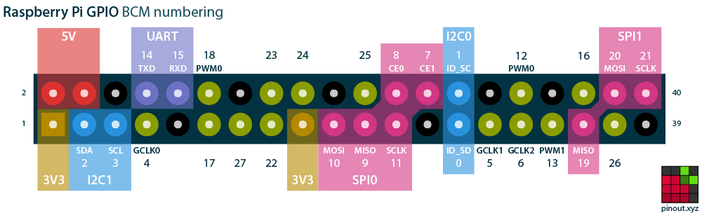
sudo apt-get install python3-serialThe pinout of the Raspberry Pi can be seen in the image below (obtained from pinout.xyz):

A large number of the GPIO pins available to us are, or can be, used for other purposes, such as I2C, SPI, and UART. The pins assigned in this project have been carefully selected to not overlap with any of these interfaces, not because they are being used in this project, but because in the scenario where their use becomes useful, the pins will not need to be moved and the code will not need to be edited. The following table describes the pin assignment used for the Raspberry Pi.
| GPIO (BCM) Pin Number | Physical Pin Number | Assignment | Input / Output | Description |
|---|---|---|---|---|
| 0 | 27 | UNASSIGNED | Used by Raspberry Pi for I2C | |
| 1 | 28 | UNASSIGNED | Used by Raspberry Pi for I2C | |
| 2 | 3 | UNASSIGNED | Used by Raspberry Pi for I2C | |
| 3 | 5 | UNASSIGNED | Used by Raspberry Pi for I2C | |
| 4 | 7 | UNASSIGNED | Used by Raspberry Pi for GPCLK, allows the Pi to be set up to output a fixed frequency without any software control | |
| 5 | 29 | UNASSIGNED | Used by Raspberry Pi for GPCLK, allows the Pi to be set up to output a fixed frequency without any software control | |
| 6 | 31 | UNASSIGNED | Used by Raspberry Pi for GPCLK, allows the Pi to be set up to output a fixed frequency without any software control | |
| 7 | 26 | UNASSIGNED | Used by the Raspberry Pi for SPI | |
| 8 | 24 | UNASSIGNED | Used by the Raspberry Pi for SPI | |
| 9 | 21 | UNASSIGNED | Used by the Raspberry Pi for SPI | |
| 10 | 19 | UNASSIGNED | Used by the Raspberry Pi for SPI | |
| 11 | 23 | UNASSIGNED | Used by the Raspberry Pi for SPI | |
| 12 | 32 | UNASSIGNED | Used by the Raspberry Pi for Hardware PWM | |
| 13 | 3 | UNASSIGNED | Used by the Raspberry Pi for Hardware PWM | |
| 14 | 8 | UNASSIGNED | Used by the Raspberry Pi for UART | |
| 15 | 10 | UNASSIGNED | Used by the Raspberry Pi for UART | |
| 16 | 36 | SAFETY INTERLOCK STATUS | OUTPUT | A combination of 2 of the Operation Mode Selector pins will signal the Arduino to switch to the corresponding operation mode |
| 17 | 11 | MODULATION MODE SELECTOR | OUTPUT | A combination of 3 Modulation Mode Selector pins will signal the Arduino to output one of the corresponding preprogrammed waveforms |
| 18 | 12 | UNASSIGNED | Used by the Raspberry Pi for UART | |
| 19 | 35 | UNASSIGNED | Used by the Raspberry Pi for SPI | |
| 20 | 38 | UNASSIGNED | Used by the Raspberry Pi for SPI | |
| 21 | 40 | UNASSIGNED | Used by the Raspberry Pi for SPI | |
| 22 | 15 | MODULATION MODE SELECTOR | OUTPUT | A combination of 3 Modulation Mode Selector pins will signal the Arduino to output one of the corresponding preprogrammed waveforms |
| 23 | 16 | OPERATION MODE SELECTOR | INPUT | Monitors the status of the safety interlock |
| 24 | 18 | OPERATION MODE SELECTOR | INPUT | Monitors the status of the safety interlock override |
| 25 | 22 | ARDUINO RESET | OUTPUT | Turning on this pin will reset the Arduino and bring back to a known safe state |
| 26 | 37 | INTERLOCK OVERRIDE STATUS | OUTPUT | A combination of 2 of the Operation Mode Selector pins will signal the Arduino to switch to the corresponding operation mode |
| 27 | 13 | MODULATION MODE SELECTOR | OUTPUT | A combination of 3 Modulation Mode Selector pins will signal the Arduino to output one of the corresponding preprogrammed waveforms |
The laser used in this project is the Coherent BioRay laser, controlled by a corresponding Coherent BioRay Controller unit, as specified in the documentation.
The back panel of the controller unit has the following connectors (alternatively, see Figure 4-2. in the documentation):

The controller unit receives power via the Power In Connector, and in turns supplies power to the laser via the Laser Head Connector into which the laser itself is connected. The BNC connector allows signals and waveforms to be sent to the laser controller, which will modulate the laser according to the following diagram (alternatively, Figure 2-1 in the documentation):

The Mini USB B connector allows commands to be sent to the laser via RS-232 over USB. The laser supports many different commands for changing the settings or getting the status of the laser (full list can be seen as Table 5-1. in the documentation), most of which will not be used in this project. The Raspberry Pi communicates directly with the laser by sending and receiving serial data via a USB A to Mini USB B cable connected to the controller.
The Arduino used in this project is the Arduino Uno, used as a smart modulation controller for the laser described above. This specific Arduino was chosen due to its small size as well as the following features:
- 5V operating voltage (same as the Raspberry Pi)
- 14 digital I/O pins (6 are hardware PWM output pins)
- 6 analog input pins
- 32KB of Flash Memory
- 2KB of SRAM
- 16MHz clock speed
According to our specification, the Arduino will need to be setup up to be able to do the following:
- receive Serial messages from the Raspberry Pi
- read GPIO pins to determine the modulation mode and operation mode
- send I2C data to a connected DAC
- generate waveforms of different shape, amplitude and frequency
- allow all waveforms to trigger camera at a user-defined threshold
- allow some waveforms to be triggered by a camera
- signal status using LED and piezo buzzer
- detect (hardware and software) the breaking of the safety interlock
- visually and audibly warn when overriding the safety interlock
This section will describe what every pin on the Arduino will be set up to do, as well as how the Arduino will be wired with other components. A very nice diagram of the full Arduino pinout can be seen on circuito.io, from which I have taken snippets and included below.
The Arduino has 14 digital IO pins, marked as 0 to 13 in purple on the diagram below:

The assignment of these digital pins is summarised as follows:
| Pin Number | Assignment | Input/Output/PWM | Description |
|---|---|---|---|
| 0 | UNASSIGNED | Used by the Arduino for serial communication | |
| 1 | UNASSIGNED | Used by the Arduino for serial communication | |
| 2 | LASER TRIGGER | INPUT | Enables connected camera to trigger laser pulses when exposing |
| 3 | CAMERA TRIGGER | OUTPUT | Enables laser to synchronise camera shutter with a generated waveform |
| 4 | MODULATION MODE SELECTOR | INPUT | Activates one of the preprogramed modulation modes |
| 5 | POWER LED | PWM | Controls intensity of green power LED |
| 6 | BUZZER | PWM | Controls tone of buzzer |
| 7 | MODULATION MODE SELECTOR | INPUT | Activates one of the preprogramed modulation modes |
| 8 | MODULATION MODE SELECTOR | INPUT | Activates one of the preprogramed modulation modes |
| 9 | [R]GB LED | PWM | Controls intensity of red colour in RGB LED |
| 10 | RG[B] LED | PWM | Controls intensity of blue colour in RGB LED |
| 11 | R[G]B LED | PWM | Controls intensity of green colour in RGB LED |
| 12 | UNASSIGNED | Unused | |
| 13 | UNASSIGNED | Used by built-in LED |
The Arduino also has 6 analog input pins, marked as A0 to A5 in green on the diagram below:

The assignment of the analog pins is summarised by the following table:
| Pin Number | Assignment | Description |
|---|---|---|
| A0 | OPERATION MODE SELECTOR | Activates one of the preprogramed operation modes |
| A1 | OPERATION MODE SELECTOR | Activates one of the preprogramed operation modes |
| A2 | INTERLOCK MONITOR | Monitors the status of the safety interlock |
| A3 | OVERRIDE MONITOR | Monitors the status of the safety interlock override |
| A4 | UNASSIGNED | Used by Arduino for I2C communication |
| A5 | UNASSIGNED | Used by Arduino for I2C communication |
It is important to note that:
- For any digital pin, the Arduino defines voltages below 0.8V as LOW and voltages above 2V as HIGH. If any digital input pin has a voltage between 0.8V and 2V, its state is "undefined". That is why it is important to use pull-down resistors (or pull-up resistors, but none have been used in this project), to make sure the pin is pulled down below 0.8V when no voltage is applied, so the pin can be read as LOW. The pull-down resistors used in the project are all 2.2 kohm.
- The recommended maximum current that a single pin can take/provide is 20mA.
- The absolute maximum current that all pins can take/provide together is 200mA.
It will sometimes be necessary to bring the Arduino back to a "known safe state", for example after a power loss of the Raspberry Pi, the internal variables of the server will need to be reinitialised and match those on the Arduino. We do this by connecting the "RESET" pin on the Arduino (see image below) to an NPN Transistor (for example, this one). The collector of the transistor would connect to the RESET pin, while the emitter would be connected to ground. The base of the transistor will be set up to connect to a pin on the Raspberry Pi, which can then trigger the reset of the Arduino.

It is important to note that, when the transistor is saturated (see here), it is essentially acting like a short-circuit and therefore damaging the transistor as well as the GPIO pin on the Raspberry Pi. Therefore, an appropriate resistor needs to be wired between the transistor base and the GPIO pin (I have used the same resistor as those used for pull-down).
A green "power" LED as well as an RGB "status" LED is used to signal different events or states that the Arduino is in. The list of all possible colour combinations, as well as their meaning, can be seen in this table:
| Status | Power LED (green) | Status LED (RGB) | Description |
|---|---|---|---|
| Power off | Off | Off | The device is not receiving power or is being programmed |
| Booting | Green | RGB cycle | The device is in the process of booting |
| Ready | Green | Off | The device is ready and waiting to receive instructions |
| Lasing (normal) | Green | Blue (continuous) | The device is device is modulating the laser with a non-zero amplitude continuous wave, sine wave, triangle wave or sawtooth wave |
| Lasing (pulsed) | Green | Blue (intermittent) | The device is modulating the laser with a square wave or a pulse train, where the RGB LED will be illuminated synchronously with the laser |
| Calibrating | Green | Magenta (continuous) | The device is undergoing a calibration pass after it has received new wave parameters. |
| Receiving data | Green | Green (continuous) | The device is receiving or parsing data received from an attached serial device |
| Safety Interlock Open | Green | Red (continuous) | The device detected that the safety interlock is open and is not being manually overridden, therefore laser modulation has been temporarily disabled. |
| Safety Interlock Overridden | Green | Orange (intermittent) | The device detected that the safety interlock is open but it is being manually override. Laser modulation is enabled but an audible warning will sound (if enabled) synchronously with the orange warning light. |
This section describes the required wiring between all the components and the Arduino, using photographs of the setup accompanied by a schematic diagram. The wiring of the entire system, including the DAC, safety gate, interlock and switch terminals, remote reset transistor, indicator LEDs, warning piezo buzzer, and camera communication connections, can be seen in the image below, followed by a full schematic.

The schematic below was created using Fritzing. The Fritzing source file is also available here. Anyone wishing to clean up this wiring and transfer it to a PCB should find the Fritzing schematic very useful.

Although care has taken to reserve different jumper colours for each "type" of connection, due to lack of sizes, some colours had to be reused. The general rule is that long green jumpers correspond to connections with Raspberry Pi GPIO pins, while long orange jumpers connect breadboard components to the Arduino, and the long yellow jumpers connect the Arduino to the camera. Additionally, mid-sized grey and white jumpers are connections between the Arduino's "analog out" pins and the breadboard. It should be noted that small jumpers with same colours have also been used for inter-breadboard connections. A more consistent colouring scheme has been used in the Fritzing schematic:
| Colour | Meaning |
|---|---|
| Black | Ground |
| Red | 5V Power |
| Brown | 0-5V Variable Power |
| Green | 3.3V Signal |
| Yellow | 5V Signal |
| Orange | 5V PWM Signal |
| Pink | I2C Signal |
| Blue | 0-5V Signal to Laser |

We will begin by looking at the main breadboard. Starting from the left of the top half, the first component (rows 1-6) is the DAC, followed by an OR gate (rows 10-17), the safety interlock override switch terminals (rows 20-21) and the safety interlock monitor terminals (rows 22-23). The bottom half contains the Arduino remote reset transistor (rows 30-32), a green power LED, a status RGB LED (rows 45-48), followed by the camera communication connections (rows 52-55), and finally the warning piezo buzzer.

This close-up highlights the connections between the DAC and the safety gate. The VOUT pin is connected to the laser via a BNC cable, and provides it a modulation signal. The SDA and SCL pins connect to Arduino's analog pins (blue-red-yellow), and allow for I2C communication with the DAC. GND is connected to the ground, while VDD is connected to the output pin of the OR gate (yellow-red-orange-grey). The OR gate is connected to 5V and ground, and takes two input. Input A is signal from the safety interlock override switch, and input B is the signal from the safety interlock. Both signals are pulled down to ground with an appropriate resistor.
It should be noted that some of the connections below are schematically correct but do not match the actual wiring, mainly due to inconsistencies between pinouts of different components.

The image below is a close-up of the safety interlock (red curl) and override (yellow curl) terminals. They are connected to the OR gate via a short blue and green jumper, respectively

The interlock and override terminals are also connected to RPi GPIO pins (via orange-green), as well as Arduino's analog-out pins (via orange-orange-(orange)-red-yellow-grey).

The next view highlights the Arduino remote reset transistor, as well as the two signal LEDs. The emitter of the transistor is connected to the ground, while base is connected to one RPi GPIO trough a current-limiting resistor. The collector connected to the RESET pin on the Arduino. The green power LED is connected to one of Arduino's PWM pins and directly to ground, and will remain on while the Arduino is on. The RBG LED is connected in a similar fashion, but uses three PWM pins for the red, green and blue pins.

The image below shows the final close up, this time of the camera communication connections and the piezo buzzer. The buzzer is connected in the same fashion as the LEDs: one pin to Arduino's PWM and the other to ground (in no particular orientation). The camera communication wires are highlighted red, pink, metallic, and brown. The red and pink wires corresponds to camera synchronisation pins, allowing the camera shutter to synchronise with the modulation waveform of the laser. They are connected to Arduino's GPIO pins, and the input pin is also pulled down to ground with an appropriate resistor. The metallic and brown pins provide isolated power and ground to the camera, for synchronisation purposes. These are connected to 5V and ground, respectively.

Here is an alternate view showing all the signalling components as well as the camera communication connections.

This final image shows all the connections leaving the Arduino. The two long yellow wires leaving the top of the Arduino (bottom of the image) connect to the camera. The orange wires on the same side lead to other components. These can be seen in more detail in the schematic, as well as in the table included in the sections above. The bottom of the Arduino has the "analog in" and "power" headers. The two white jumpers are used for I2C communication with the DAC, while the grey jumpers are used for other digital-through-analog connections. The green wire from the power header provides ground for the breadboard (-) rail, while the yellow provides 5V for the (+) rail. Finally, the grey jumper from the power rail connects the RESET pin to a transistor.

This is the schematic view of the image above. The colours are consistent with the system described above. Note that this is a rotated view of a part of the schematic.

The digital-to-analog converter (DAC) used in the project is the 12-bit MCP4725 on an Adafruit breakout board. A useful tutorial by Adafruit on how to use the DAC with both Arduino and Raspberry Pi can be found here.
The DAC receives data from the Arduino using the I2C interface, where the DAC is the slave device and Arduino is the master. The DAC's SCL and SDA pins connect directly to Arduino's SCL [A5] and SDA [A4] pins. The DAC receives 5V through its VDD pin, and can output any voltage between 0V and 5V with a 12-bit accuracy through its VOUT pin.
Instead of the DAC being connected directly to Arduino's 5V output, it is powered through a logical OR gate (see datasheet) which takes two inputs: safety interlock, and interlock override. If the safety interlock is open (safety interlock line goes LOW), and the interlock override is not switched on (override line is also LOW), the gate will switch off the 5V output. As the DAC loses power, it can no longer output any signal, thereby modulating the laser beam to zero.
Additionally, once the DAC's power returns (either the interlock is closed or the override is turned on), the DAC's EEPROM has been set up so that it resumes to a safe state (output of 0V). The DAC will therefore have to be explicitly told to restart modulating the laser.
The Arduino has been programmed with 6 different modulation modes. If modulation is set to none, a waveform will not be generated, but a continuous wave of adjustable amplitude will be outputted. At an amplitude of 100%, the laser output looks like the image below, and looks analogous to how it operated before this project.

The amplitude of the continuous wave can be set to any value between 0% and 100%. Here is the oscilloscope output for a continuous wave, this time at 42% amplitude.

The second modulation mode is sine. This mode generates a sine wave with a custom amplitude and period. The image below shows a sine wave at 100% amplitude with a period of exactly 100 milliseconds.

The amplitude of any wave can be changed. For the sake of brevity, not every waveform will be included with a range of amplitudes in this documentation. The following image is also a 100 millisecond sine wave, but this time with an amplitude of about 42%

An additional parameter can be specified for any wave: the delay between every successive cycle. The wave below is a 100ms period wave with a delay of 200ms between waves, creating a total period of exactly 300ms.

If the operation mode of the Arduino is set to master, then the Arduino will output a HIGH when the amplitude of a wave reaches a user-defined threshold. This output, shown in blue, can be used to synchronise the laser modulation with the shutter of a camera (for example, only exposing when the laser is illuminating the sample adequately).

The previous image showed the trigger threshold at 50%. The following image shows the behaviour when the threshold is raised to 80%

The period of the sine wave can be as high as 1 second. The image below shows this wave being generated fairly accurately, only 1.1% above the target period. Periods higher than 1 second are disabled, as above this value, you should consider switching to continuous-wave mode.

The period of the sine wave can also pushed a lot lower than 100ms, but with some disadvantages. The image below shows a sine wave with a target period of 10ms, with a true value of 0.9% above the target. The wave is no longer smooth, and the time it takes for the DAC to update the voltage and the Arduino to calculate the next point on the wave becomes visible.

When this period is pushed even lower, the generated wave looks less like a sine wave and instead resembles a triangle wave. The target period of this wave is 2ms, but it is being generated with a period 16.7% higher than the target - a value no longer considered acceptably accurate.

At the smallest possible period, the wave is no longer a sine wave. The square wave generated below is a sine wave with a target period of 1ms. The actual period is also 32.7% larger than the target. Due to this increase in inaccuracies with decreasing period targets, periods under 10ms are considered "inaccurate", and should only be used if higher frequencies are necessary (but using square as your modulation mode would give even higher frequencies with much higher accuracy).

The same behaviour can be seen across other waveforms as well. The images below are for the triangle and sawtooth modulation modes.
 |
 |
|---|---|
| Triangle wave at 100ms target (exact) | Triangle wave at 1ms target (+7.9%) |
 |
 |
|---|---|
| Sawtooth wave at (1s) 1000ms target (+0.4%) | Sawtooth wave at 1ms target (+41.2%) |
The final modulation mode available is pulse. A single pulse is defined by three parameters: the amplitude of the pulse, the length of the pulse, and the delay until the start of the successive pulse. This mode allows for pulses of length up to 1 hour, and as little as a millisecond. The following image shows a 100 millisecond pulse followed by a second pause, resulting in a perfect 1.1 second period.

The following data gives the exact limits applied to the selection of the period for various modulation modes, and their measured corresponding deviations from the expected value:
| Modulation Mode | Period Limits | Needs calibration | Calibration Length | Typical [maximum] deviation (10ms - 100ms) | Typical [maximum] deviation (< 10ms) |
|---|---|---|---|---|---|
none |
none | No | N/A | N/A | N/A |
sine |
1ms - 1s | Yes | 5s - 10s | +1% [+2%] | +20% [+50%] |
square |
1ms - 1hr | No | N/A | +0.5% [+1%] | +5% [+10%] |
triangle |
1ms - 1s | Yes | 5s - 10s | +1% [+2%] | +20% [+50%] |
sawtooth |
1ms - 1s | Yes | 5s - 10s | +1% [+2%] | +20% [+50%] |
pulse |
1ms - 1hr | No | N/A | +0.5% [+1%] | +5% [+10%] |
The camera used in this project is the Allied Vision Manta. It uses the Hirose HR10-10R-12PA(73) connector, for which we used the Hirose HR10A-10P-12S breakout cable. The pin numbering for the Hirose cable can be seen below:

According to the input block diagram below (as well as Figure 109 in the documentation), both pins In1 and In2 are available as general purpose input pins, when connected to some isolated ground.

Similarly, the output block diagram below (as well as Figure 111 in the documentation) shows that pins Out1 and Out2 are available to use as general purpose output pins when the block is connected to some isolated power source, and the pins are pulled LOW using pull-down resistors. If the isolated power input is 5V, then both GPO pins will also signal at 5V.

With this knowledge, it is possible to create a pin assignment table:
| Pin Number | Signal | Assignment |
|---|---|---|
| 4 | In1 |
This pin can receive signal from the Arduino, and will synchronise the shutter of the camera with respect to the modulation waveform |
| 6 | Out1 |
This pin will receive signal when a generated waveform amplitude reaches a threshold, triggering the shutter of the camera |
| 7 | Isolated In GND | This pin is tied to Arduino's GND pin |
| 10 | Isolated Out PWR | This pin is tied to Arduino's 5V pin |
CRATE A FILE FROM THIS AND HOST IT, AND CLEAN IT UP, LIKE ABOVE
[Unit] Description=Python3 server After = multi-user.target network.target network-online.target Wants = network-online.target
[Service] Type=idle Restart=always ExecStart=/usr/bin/python3 /home/pi/server.py
[Install] WantedBy=multi-user.target
/lib/systemd/system/server.service
(change to table of return codes?) (change warnings to stackable! 01+02+04 (up to 16?))
| Return Code | Return Code type | Description | More details given? |
|---|---|---|---|
| 00 | SUCCESS | The requested action completed without error or warning | No |
| 01 | WARNING | The requested action was not carried out as it would have no effect | No |
nohup
https://raspberrypi.stackexchange.com/questions/9695/disable-dtr-on-ttyusb0/31298#31298
https://linux.die.net/man/1/stty
At the core of the Arduino Uno lies the Atmel ATmega328p microcontroller.
<MODES OF OPERATION, MODES OF MODULATION>
talk about why I had to replace the Wire library
http://dsscircuits.com/articles/arduino-i2c-master-library
changed compilation parameter to -O2 (talk about it) File --> Preferences --> Follow link at the bottom of page (using arduino 1.8.5) "%USERPROFILE%\AppData\Local" on Windows, C:\Users\lyv26778\AppData\Local\Arduino15\preferences.txt, change all occurences (3) of -Os to -O2, restart Arduino IDE
Talk about me quickly, mention contact details, give supervisor details as well
Same as pptx, + Hristo and Jess

