Comments (13)
 BrushlessPower
commented on June 20, 2024
BrushlessPower
commented on June 20, 2024
Dear Chema,
i think there is a mismatch of your 18SZ Sensor Settings and the Arduino Sensor Settings.
try to keep it simple:
remove all unused Sensors in Arduino and in your 18SZ
Watch out your Slot Settings, they must be the same in arduino and 18SZ
Fur further help i would be good to post a picture with your 18SZ Slot Settings.
The fact, that the RPM is working, shows that your Hardware and Modulation is working. the Rest is just Firmware and Settings.
Please do not use a Variometer. It's not supported yet.
you have to use GPS Sensor "F1675"
For Temp125 use "F1713" or "SBS/01TE" if there is no temp125 Sensor in your 18SZ
from sbus2-telemetry.
 flyingsinver
commented on June 20, 2024
flyingsinver
commented on June 20, 2024
Thank you very much for your quick response
I think I have understood you
Tonight i will check
I edited the link for pics
https://drive.google.com/file/d/1NBS2yBeSfRPz0MLVWmmkfSwXrp879I96/view
https://drive.google.com/file/d/1qUmKyzaBxOAnVxb1mKAuKPJhlGejBZo3/view
https://drive.google.com/file/d/1Jl31XbzBUovFmRNBtNpjTzZlcI4S-0z4/view
I am very happy to have established communication with you !!!
Thank you very much again
from sbus2-telemetry.
flyingsinver
commented on June 20, 2024
Niceeeeeeee !!! Thanks thanks thank you very much my friend !!!
Thank you for your help !!!
I've seen in another thread this comment of yours also helping wienne
.INO file:
#define VOLTAGE_SLOT 16 // 2 Slot Sensor
in loop add:
send_voltage(VOLTAGE_SLOT,(uint16_t)128, (uint16_t)255); // Voltage1 = 12.8V, Voltage2 = 25.5V
in SBUS2.cpp add:
void send_voltage(uint8_t port,uint16_t voltage1, uint16_t voltage2)
{
uint16_t value = 0;
uint8_t bytes[SBUS2_TEL_DATA_SIZE] = {0x03, 0x40, 0x00 };
// VOLTAGE1
value = voltage1 | 0x8000;
if ( value > 0x9FFF )
{
// max voltage is 819.1
value = 0x9FFF;
}
bytes[1] = value >> 8;
bytes[2] = value;
SBUS2_transmit_telemetry_data( port , bytes);
//VOLTAGE2
value = voltage2;
if ( value > 0x1FFF )
{
// max voltagee is 819.1
value = 0x1FFF;
}
bytes[1] = value >> 8;
bytes[2] = value;
SBUS2_transmit_telemetry_data( port+1 , bytes);
}
in SBUS2.h add:
void send_voltage(uint8_t port,uint16_t voltage1, uint16_t voltage2);
I think it is the modification that I also need to add two additional voltage measurements on board my plane and have four voltage measurements in total for the 4 LiPo 2S batteries that I will install since everything will work at 7.4V
In the absence of the configuration of the additional voltages I leave some photos of the menus of Futaba configuring the sensors, I think they are well indeed seems to work correctly
https://drive.google.com/file/d/1Kik4Rcfz_t6tFIAHXhREoIEbcLuXQHgL/view
https://drive.google.com/file/d/1KjgXWEQoix7WyCnaaA4uJ7w-DXlLr5-1/view
https://drive.google.com/file/d/1KjuiLZct-r2aV9DYVtkh8rxrMl2aIDQS/view
https://drive.google.com/file/d/1L4WmTB7ck1o71JlLxAEuTU-G57gnrw0H/view
https://drive.google.com/file/d/1LDZ8cT5g7SGfZ9YT65cBIls0I70FNEmF/view
https://drive.google.com/file/d/1LFEi697SfE1F8m2D7jxqhnlEY2DT7efX/view
also a litte video of a dynamic simulation ( no real hardware data adquisition )
https://www.youtube.com/watch?v=q_-Rb75BchQ
I will continue moving forward with my project thanks to you !!!
Sincerely,
Chema
from sbus2-telemetry.
BrushlessPower
commented on June 20, 2024
Nice to hear that it's working.
Most Issues are related to wrong Setting. I plan to write a "How to" with the Release of Version 1.0.
In Version 1.0 i will add the Voltage Sensor and the Vario's
Can i user your pictures of the 18SZ Settings for the How to?
Maybe it would be nice to place the Github Link to the Youtube Video.
Did you build your Inverters on your own? Or did you buy something? Because it looks very nice and clean.
Greetings John
from sbus2-telemetry.
flyingsinver
commented on June 20, 2024
Hello Jonh !!!
-Can i user your pictures of the 18SZ Settings for the How to?
Of course, it will be a pleasure to contribute a grain of sand although very small to your enormous contribution!
Maybe it would be nice to place the Github Link to the Youtube Video.
good idea, done !!!
Did you build your Inverters on your own? Or did you buy something? Because it looks very nice and clean.
I made it but they are the transistors and the resistances of their scheme, this:
https://github.com/BrushlessPower/SBUS2-Telemetry/blob/master/SBUS2_inverter.png
John, when do you plan to publish the new version ?
Could you extract the value of the RSSI signal from the SBUS and reinject it again as a numerical value from 0 to 100 in percentage or in dB?
Could this be possible?
In this way we would know more exactly as the radio signal arrives at our receiver since now there is only a very small graphic in the display at the top left with the coverage stripes symbol as in mobile phones.
Thanks a lot again for everything
Best regards,
Chema
from sbus2-telemetry.
BrushlessPower
commented on June 20, 2024
when do you plan to publish the new version ?
difficult to say. Maybe tomorrow, maybe in some month. I need some free time to test the new code and make a Wiki/How to.
But actual i'am very busy with other stuff.
Could you extract the value of the RSSI signal from the SBUS and reinject it again as a numerical value from 0 to 100 in percentage or in dB?
That's not so easy. Because i cant find any information about the RSSI (FER -> Frame Error Rate) in the SBUS2 Protocol. Its there, but i don't know where. I will try to get some Information's an add this as a own issue.
But at the End, it will be just a value in Code. You have to send this value as a Temperature (Temp125 Sensor) and set up a alarm on your 18SZ if Temperature exceeds the limit.
Because Futaba has no "RSSI Sensor"
Greetings John
from sbus2-telemetry.
flyingsinver
commented on June 20, 2024
Ok ok I understand John
In the end this kind of thing is done when you can
If the RSSI data can be implemented, could it be displayed as m / s "monitor signal" or in the worst case as V "value"?
I say it because having that data as ºC is not pretty
I continue with my project thanks to you
Now I am trying to visualize the two additional voltages and finally the actual rpms read to the engine's own electronic ignition so as not to have to use an additional sensor
I will keep informing
best regards,
Chema
from sbus2-telemetry.
 wienne
commented on June 20, 2024
wienne
commented on June 20, 2024
Multiple temperature sensor functions can be implemented.
The key is the definition of the slot number in the program code.
As well as the choice of sensor model in the remote control.
The value of the fifth temperature sensor is 0, because my chip wiring is a little problem.
Sometimes I can see the value when I touch the wire lightly.


http://www.egotop.com/~sunjun/sbus2/sbus2-1.jpg
http://www.egotop.com/~sunjun/sbus2/sbus2-2.jpg
http://www.egotop.com/~sunjun/sbus2/sbus2-3.jpg
`
#define TEMP_SLOT_1 1 // 第1个温度传感器,占1个槽位,起始插槽 1-31
#define TEMP_SLOT_2 2 // 第2个温度传感器,占1个槽位
#define TEMP_SLOT_3 3 // 第3个温度传感器,占1个槽位
#define TEMP_SLOT_4 4 // 第4个温度传感器,占1个槽位
#define TEMP_SLOT_5 5 // 第5个温度传感器,占1个槽位
#define ERROR_SLOT 6 // 占1个槽位,用于程序排错,利用温度传感器显示SBUS2的错误代码
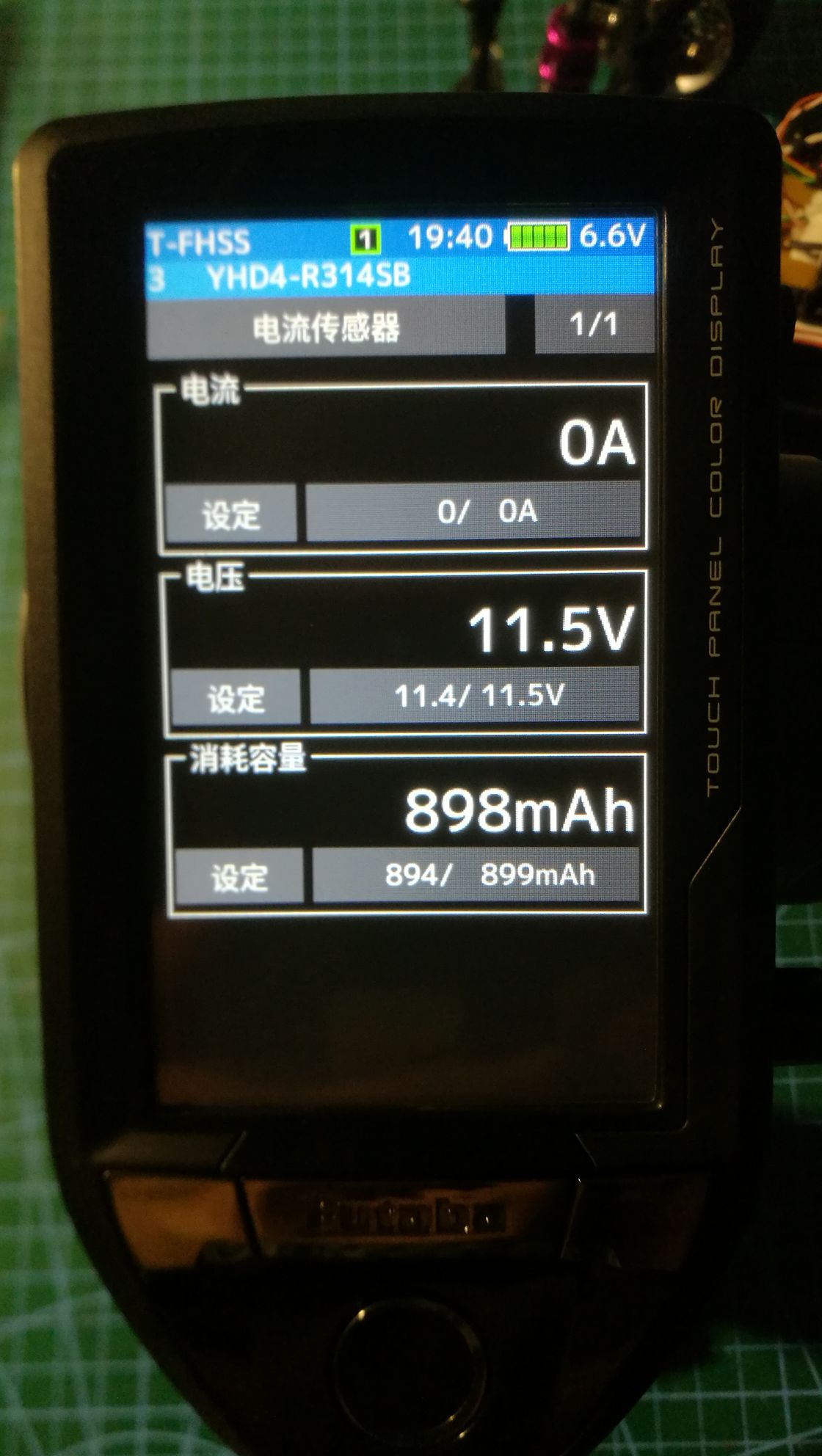
#define CURRENT_SLOT 8 // 电流传感器,占3个槽位,其中有电流、电压、容量三种数值
//CURRENT_SLOT 9,电流传感器,在第8槽时,还将占用、9和10槽。
//CURRENT_SLOT 10
//起始插槽,只能为1-5、8-13、16-21、24-29
#define VOLTAGE_SLOT 11 // 2 Slot Sensor 电压传感器,有两个电压值
//起始槽号只能为1-6、8-14、16-22、24-30
`
from sbus2-telemetry.
wienne
commented on June 20, 2024
`
#define TEMP_SLOT_1 1 // The first temperature sensor, occupying one slot, starting slot 1-31
#define TEMP_SLOT_2 2 // 2nd temperature sensor, occupying 1 slot
#define TEMP_SLOT_3 3 // 3rd temperature sensor, occupying 1 slot
#define TEMP_SLOT_4 4 // 4th temperature sensor, occupying 1 slot
#define TEMP_SLOT_5 5 // 5th temperature sensor, occupying 1 slot
#define ERROR_SLOT 6 // Occupies 1 slot, used for program troubleshooting, and uses the temperature sensor to display the error code of SBUS2
#define CURRENT_SLOT 8 // Current sensor, which occupies 3 slots, including current, voltage, and capacity values
// CURRENT_SLOT 9, the current sensor will also occupy slots 9 and 10 in slot 8.
// CURRENT_SLOT 10
// The starting slot can only be 1-5, 8-13, 16-21, 24-29
#define VOLTAGE_SLOT 11 // 2 Slot Sensor voltage sensor with two voltage values
// The starting slot number can only be 1-6, 8-14, 16-22, 24-30
`
from sbus2-telemetry.
flyingsinver
commented on June 20, 2024
hello
ok ok i understand it thank you very much wienne
I just successfully implemented the additional voltages this is starting to look great
a question for both or for the code creator
What exactly is this line for in the send loop?
what would happen if i remove it? Is it totally necessary?
send_alarm_as_temp125(ERROR_SLOT, ((failsave1000) + (transmision_dropt_frame100) + uart_dropped_frame)); // Warning with over Temp at Error Slot
thks !!!!
from sbus2-telemetry.
wienne
commented on June 20, 2024
This line of code, according to my actual test, if deleted, does not affect the use of other sensors.
According to the naming of variables in the code, I guess it is related to errors, such as interference during signal transmission, packet loss, or data related to RSSI.
I hope the author John can explain this in more detail.
from sbus2-telemetry.
BrushlessPower
commented on June 20, 2024
send_alarm_as_temp125(ERROR_SLOT, ((failsave1000) + (transmision_dropt_frame100) + uart_dropped_frame)); // Warning with over Temp at Error Slot
This code is just a Temperature Sensor with special Values.
You can remove it.
The Sensor should always Display Zero on your Futaba Screen
if the receiver indicate the failsafe Flag -> your Screen shows 1000°C
if there was a transmission problem -> your Screen shows 100°C
if there was a internal UART decoding Problem -> Your Screen shows 1°C (increasing with every problem)
For Developing & testing it's a nice "Sensor" to show problems with your Hardware
With older Versions of this Library it was a normal thing that some Errors occur. Now its more stable and it really should be 0°C
from sbus2-telemetry.
BrushlessPower
commented on June 20, 2024
should be solved?!
from sbus2-telemetry.
Related Issues (20)
- Telemetry not working with 3 sensor HOT 50
- [ESP32] Wrong Timing with ESP32 Arduino Core 1.0.5 HOT 1
- Frame loss HOT 13
- Reading SBUS2 sensor data to serial monitor HOT 34
- GPS Altitude not working
- [Feature Request] SBUS2 Frame Generation
- [BUG] UART_dropped_frame never cleared
- [ESP32][BUG] Not working with ESP32 Arduino V2.0.0 HOT 6
- GPS SBS-02G HOT 33
- [Feature] Add JetCat V10 Sensor HOT 3
- [Feature] Support ESP32-S2 & ESP32-C3 & ESP32-S3 HOT 23
- Examples don't actually compile for ESP-32: HOT 4
- How do you login your Arduino sbus2 for the remote controller?
- How do you login your Arduino as a sbus2 device to your remote controller? HOT 15
- too many arguments to function 'void SBUS2_Setup()' HOT 1
- It doesn't work with R7108SB HOT 9
- Atmega328P - jamming when processing sensors HOT 2
- Send RPM value to receiver HOT 13
- Why is there 2 voltages available for the SBS01T ? HOT 5
- SBUS Channel data HOT 27
Recommend Projects
-
 React
React
A declarative, efficient, and flexible JavaScript library for building user interfaces.
-
Vue.js
🖖 Vue.js is a progressive, incrementally-adoptable JavaScript framework for building UI on the web.
-
 Typescript
TypeScript is a superset of JavaScript that compiles to clean JavaScript output.
-
TensorFlow
An Open Source Machine Learning Framework for Everyone
-
Django
The Web framework for perfectionists with deadlines.
-
 Laravel
A PHP framework for web artisans
-
D3
Bring data to life with SVG, Canvas and HTML. 📊📈🎉
-
Recommend Topics
-
javascript
JavaScript (JS) is a lightweight interpreted programming language with first-class functions.
-
web
Some thing interesting about web. New door for the world.
-
server
A server is a program made to process requests and deliver data to clients.
-
Machine learning
Machine learning is a way of modeling and interpreting data that allows a piece of software to respond intelligently.
-
Visualization
Some thing interesting about visualization, use data art
-
Game
Some thing interesting about game, make everyone happy.
Recommend Org
-
Facebook
We are working to build community through open source technology. NB: members must have two-factor auth.
-
Microsoft
Open source projects and samples from Microsoft.
-
Google
Google ❤️ Open Source for everyone.
-
Alibaba
Alibaba Open Source for everyone
-
D3
Data-Driven Documents codes.
-
Tencent
China tencent open source team.
from sbus2-telemetry.